As is typical for QUAD work, we had to iterate through a 2nd First Contact cleaning on the ETMY today which prevented us from closing out BSC10 today.
Recall, yesterday we applied First Contact to the ETMY HR surface (cone spray, with painted on reinforced edge. This morning we
- continued to clean the suspension and optics a little more (gingerly so as to not migrate particulate to areas we don't want it in (nooks and crannies around fibers, the back side of ETMY).
- we prepped the suspension for closeout via setting the top 4 ETMY BOSEMs to account for buoyance, and locked all of the nuts on ~60 plus barrel and face EQ stops (I could see particulate fall off of the silver plated nuts here and there as I did this with my tools and flashlight).
- blew the TMS lowest telescope large mirrors to clear them of particulate.
- we pulled the ACB back down into place and secured it.
- wiped a few spotty surface on the TMS, and we wiped the floor more.
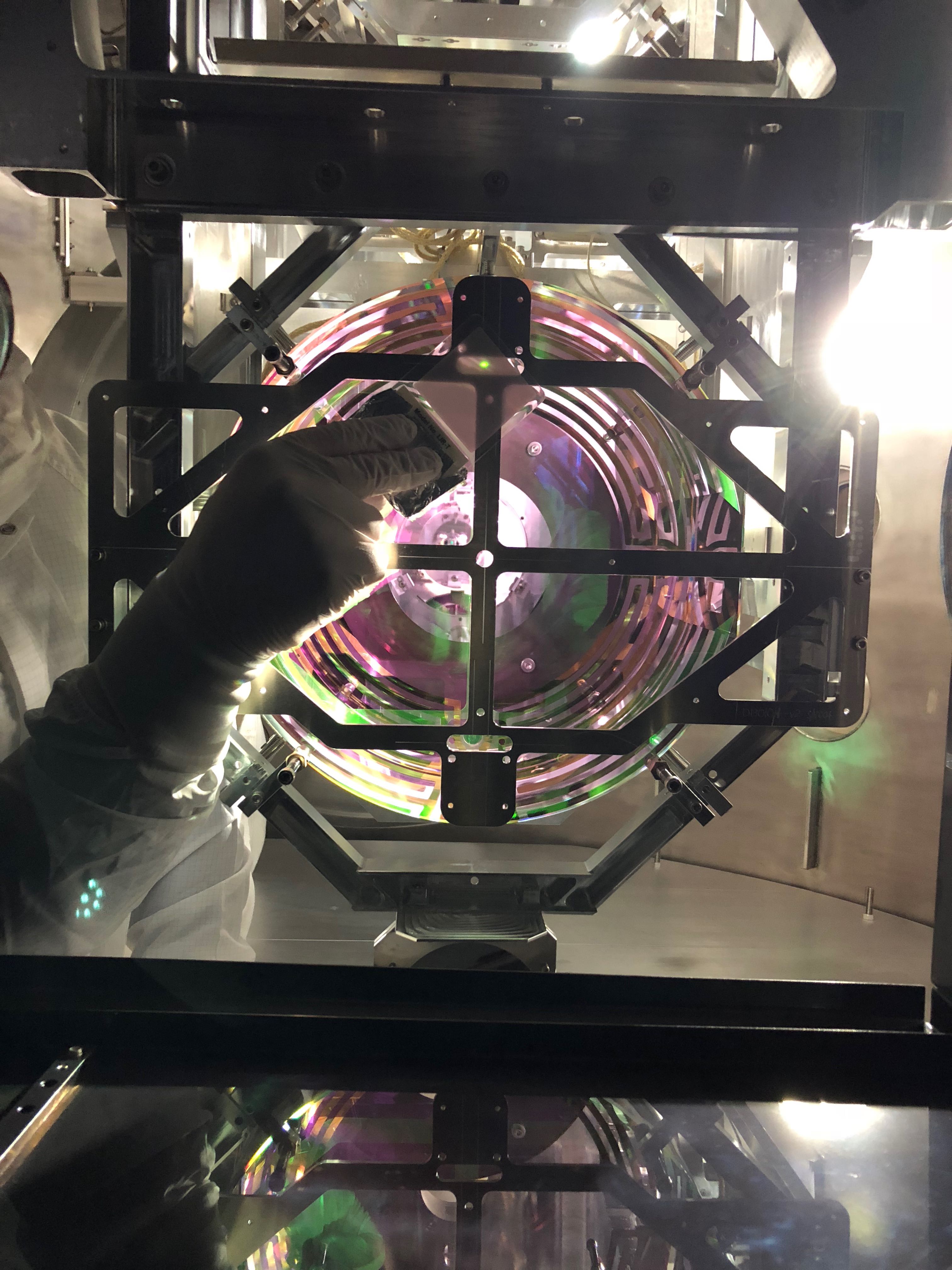
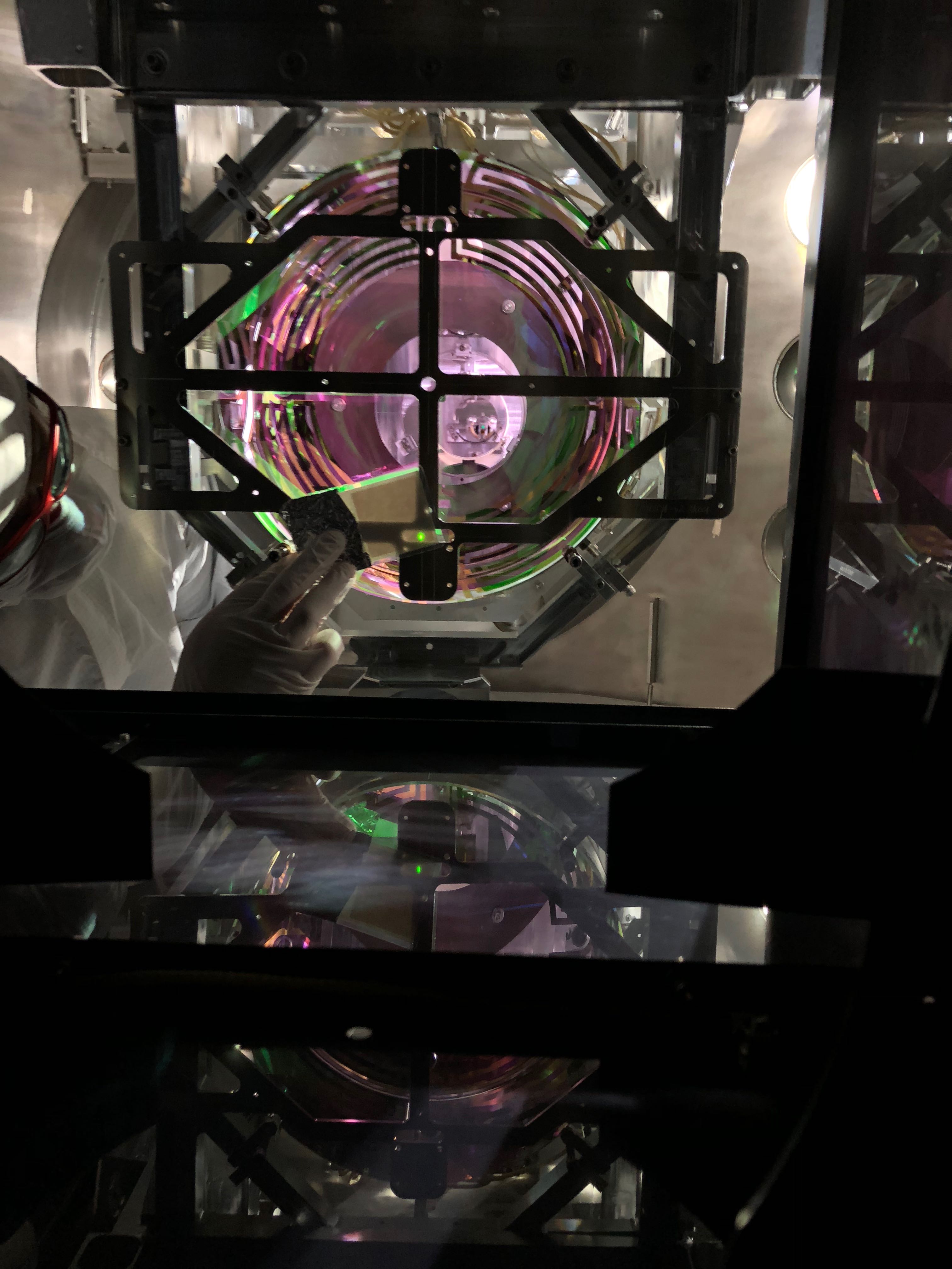
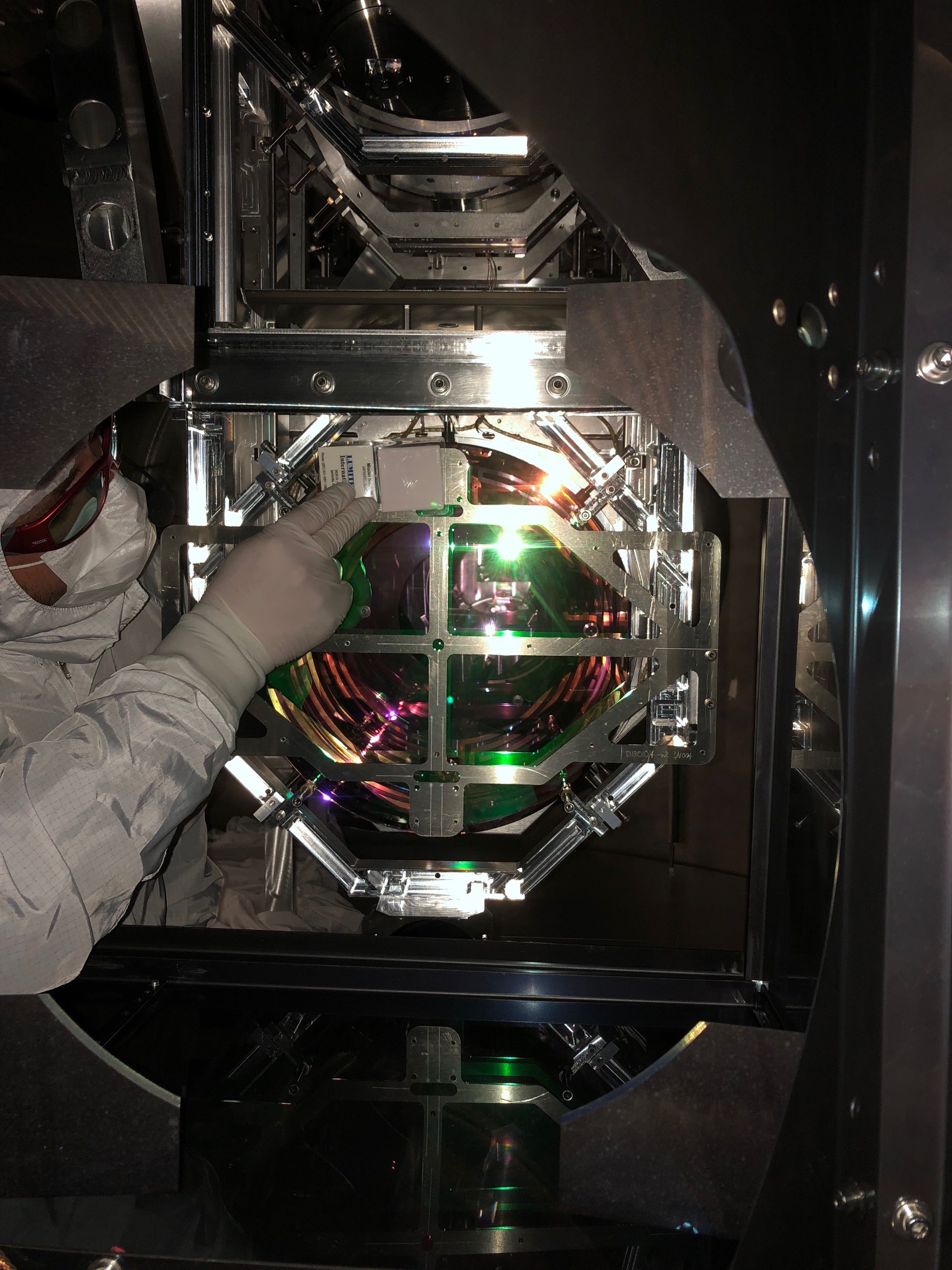
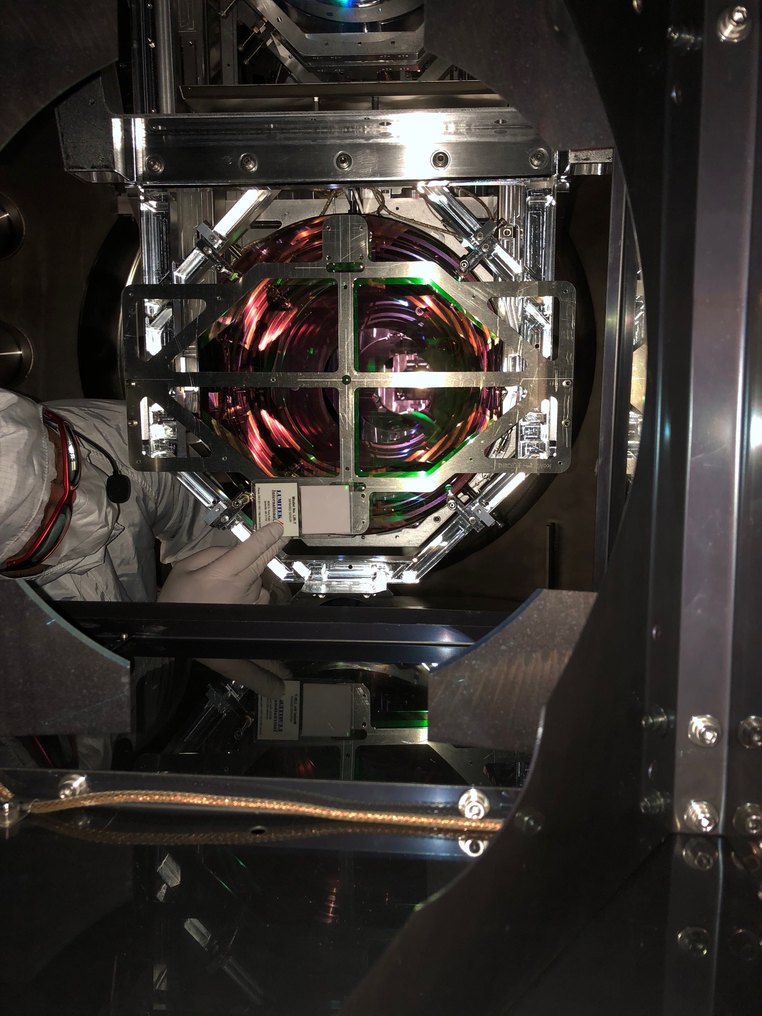
- with Jim and the door crew on hand, we then pulled the First Contact. Things looked good with the pull until I inspected further and found 2 very small (sub mm x 1mm long) streaks of FC nearish the center of the optic. Darn. Abort.
We then called off the ISI unlocking/door crews, put the ACB back, reattached the cone and did another round of FC spray and paint application.
We'll go back at in in the morning.