Activity Summary:
- EY: Pcal
- MY: maintenance, chiller
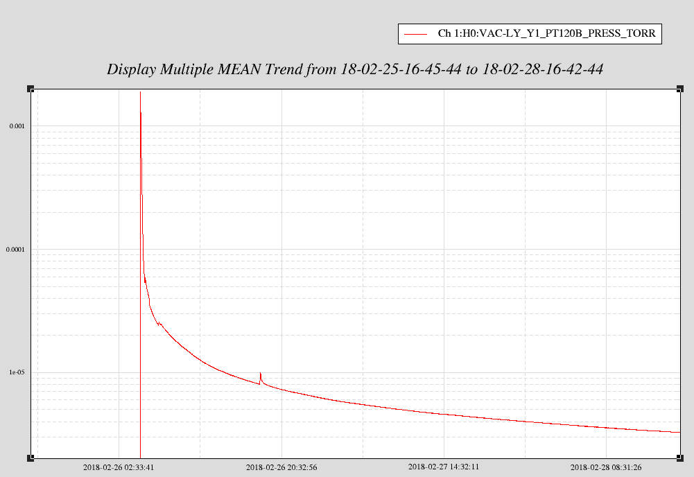
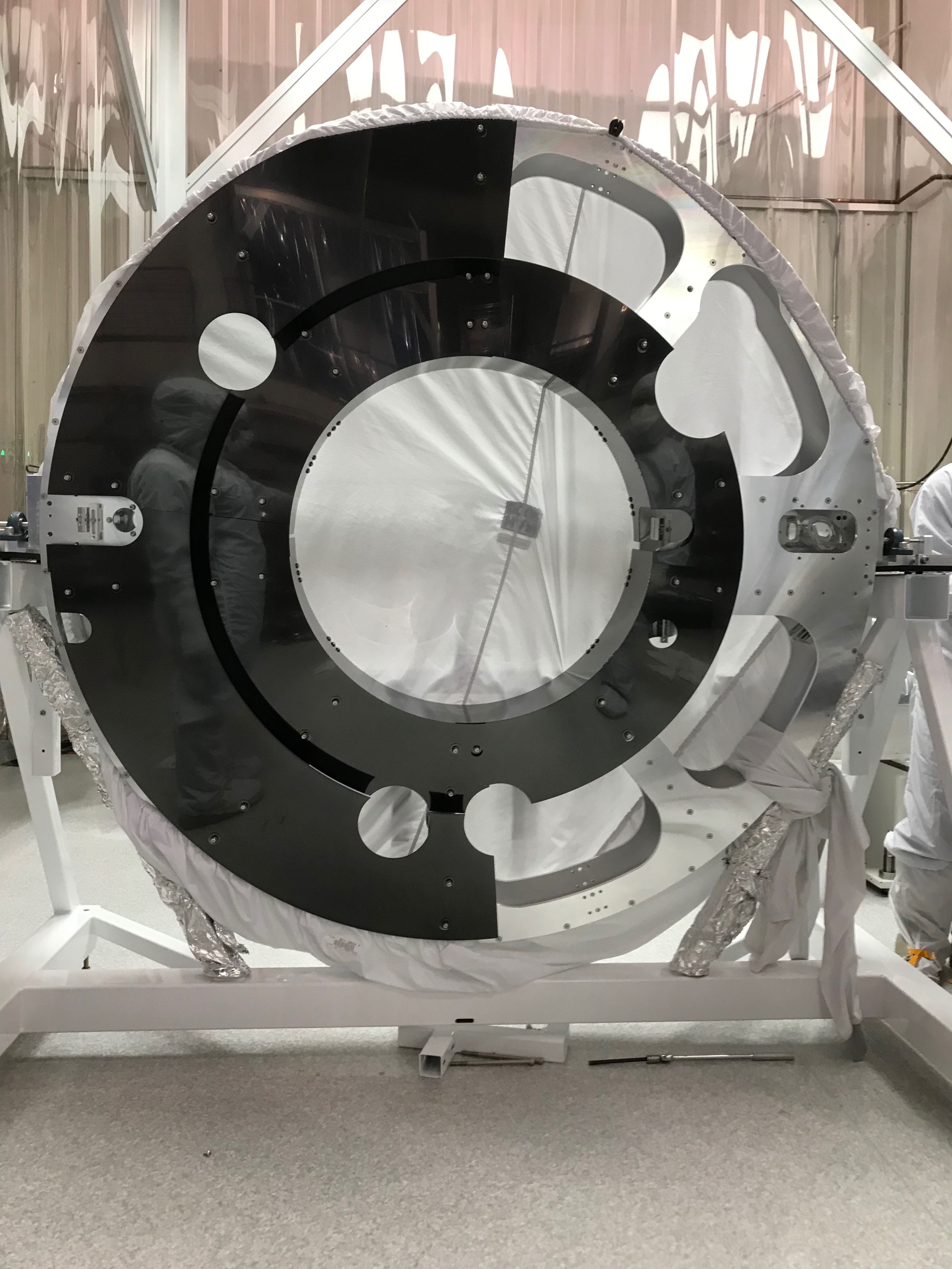
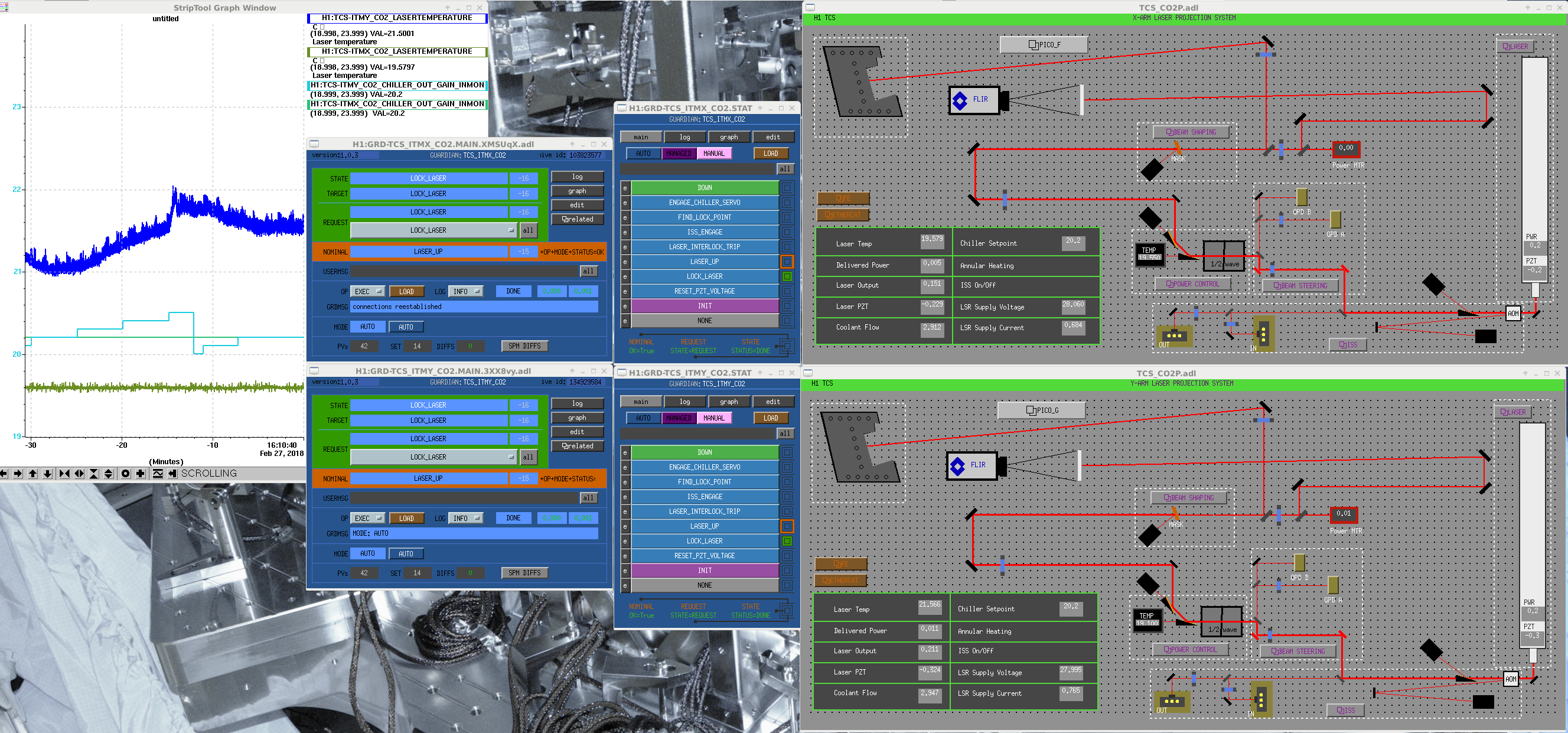
- CS: HAM6: are off, SQZ table put in place, TCS chiller hardware test
- MX: Chandra, Kyle, and MCE engineer
- EX: Fil access system
Still at outbuildings:
- EY: Gerardo
- MY: Kyle
- MX: Chandra
Activity Details (all times UTC):
28-02-18 15:35 ChrisS to MY to drop off insulation for bakeout
28-02-18 15:54 Rick at EY, Pcal
28-02-18 16:05 Terry to SQZ bay
28-02-18 16:42 Terry out of the SQZ bay
28-02-18 16:40 Hugh to LVEA
28-02-18 16:55 Rick called, EY is laser safe
28-02-18 16:58 Hugh out of the LVEA
28-02-18 17:07 Hugh de-isolating the BS HEPI, then re-isolating
28-02-18 17:08 Hanford Fire Department at EX testing sensors
28-02-18 17:08 Janson and Ed to the PSL
28-02-18 17:21 Alena and Micheal to EY
28-02-18 17:22 Travis to EY
28-02-18 17:26 Corey to SQZ bay and then optics lab
28-02-18 17:27 Jim and Stephen to EY
28-02-18 17:33 TJ to HAM6
28-02-18 17:43 TJ back from optics lab
28-02-18 18:11 TJ to HAM6
28-02-18 18:18 Jaimie starting work on new Guardian machine, currently getting a work permit
28-02-18 18:18 Fil Liz and Diesy to EX to work on access system
28-02-18 18:24 Mike and visitor to LVEA
28-02-18 18:45 Mike and visitor out of the LVEA
28-02-18 17:40 Travis back from EY
28-02-18 19:15 Betsy and Travis to EX to stage for in-vacuum work
28-02-18 19:15 TJ out of the LVEA
28-02-18 19:40 Fil, Liz, and Deisy back from EX
28-02-18 19:48 Jason and Ed to PSL
28-02-18 19:56 Betsy and Travis back from EX
28-02-18 20:20 Terry and Sheila to SQZR bay
28-02-18 20:22 Karen done at MX
28-02-18 20:25 Fil to TCS to install new limiter hardware
28-02-18 20:50 Fil, Liz, to HAM6 to work on cabling
28-02-18 21:00 Corey to EY with 2" optics
28-02-18 21:08 Gerardo to MY to remove a cable for use at MX
28-02-18 21:10 Arm Crew: Mark and Mark and TJ, taking the arm off HAM6
28-02-18 21:11 Arm crew will be opening the rollup door
28-02-18 21:12 Arm crew will ensure the HAM6 soft cover is on while the rollup door is in use
28-02-18 21:18 TJ to HAM6
28-02-18 21:19 Karen done at MY
28-02-18 21:23 Nutsinee to HAM6
28-02-18 21:24 Chandra to LVEA
28-02-18 21:27 Dave changes oplog
28-02-18 21:50 Nutsinee back from LVEA
28-02-18 21:50 Corey back from EY
28-02-18 21:51 Travis to LVEA
28-02-18 21:51 Rick to LVEA
28-02-18 21:59 Rick back from the LVEA
28-02-18 22:02 Travis, Rick, and Niko, to EY for Pcal work
28-02-18 22:05 JeffB to LVEA to retrieve parts
28-02-18 22:36 MarkP to LVEA to delver cables
28-02-18 22:37 MarkP back from LVEA
28-02-18 22:37 DaveB to Mezz to check on chillers
28-02-18 22:37 Chandra to MY
28-02-18 22:54 Richard to old PSL chiller closet and then HAM6
28-02-18 23:12 Betsy to LVEA for supplies
28-02-18 23:13 DaveB to CER to disconnect the TCS FE input to the newly installed summing box
28-02-18 23:17 Mark and Mark done at HAM6, arm is off, SQZ table is placed
28-02-18 23:20 DaveB to TCS chillers to read the setpoint from the chiller display
28-02-18 23:32 Rick, Travis, Niko, Marik, leaving EY
28-02-18 23:32 EY is laser safe
28-02-18 23:48 Patrick restarting Beckoff Laser Safety Code
28-02-18 23:56 Gerardo to MY to assist Kyle, then on to EY
28-02-18 23:57 Rick, Travis, Niko, Marik, back from EY
Hey, look, there's an updated oplog format! Original format for date and time was l-o-n-g. Shortened the numerical date, dropped the seconds for time, and dropped the callout of UTC.
Feb 27 2018 15:25:45 UTC ChrisS to all out buildings for FAMIS/Maint.: fire ext. charging lifts
28-02-18 15:35 ChrisS to MY to drop off insulation for bakeout
Update, as of 00:32UTC, all times in UTC:
01-03-18 00:16 Patricks done restarting code
01-03-18 00:16 Liz back from LVEA, Fil still at HAM6
01-03-18 00:27 Gerardo is back from EY
01-03-18 00:28 Jason and Ed done in the PSL