ivey.zhong@LIGO.ORG - posted 09:32, Tuesday 22 July 2025 - last comment - 14:32, Friday 26 September 2025(85907)
OSEM calibration of H1:SUS-SR3
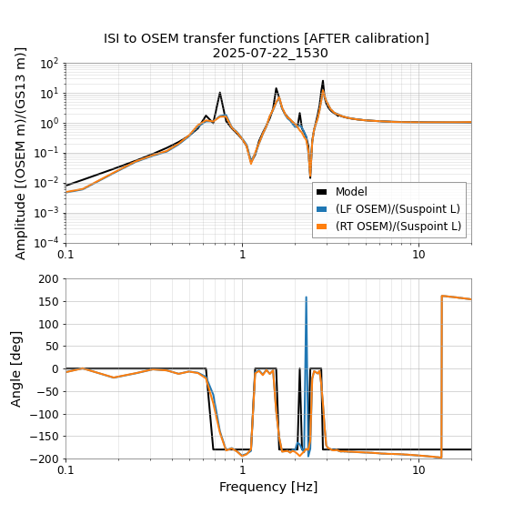
OSEM calibration of H1:SUS-SR3
Stage: M1
2025-07-22_1530 (UTC).
The suggested (calibrated) M1 OSEMINF gains are
(new T1) = 2.174 * (old T1) = 3.213
(new T2) = 1.610 * (old T2) = 1.517
(new T3) = 1.569 * (old T3) = 1.494
(new LF) = 1.331 * (old LF) = 1.733
(new RT) = 1.374 * (old RT) = 1.494
(new SD) = 1.390 * (old SD) = 1.793
To compensate for the OSEM gain changes, we estimate that the H1:SUS-SR3_M1_DAMP loops must be changed by factors of:
L gain = 0.740 * (old L gain)
T gain = 0.719 * (old T gain)
V gain = 0.545 * (old V gain)
R gain = 0.545 * (old R gain)
P gain = 0.629 * (old P gain)
Y gain = 0.740 * (old Y gain)
The calibration will change the apparent alignment of the suspension as seen by the at the M1 OSEMs
NOTE: The actual alignment of the suspension will NOT change as a result of the calibration process
The changes are computed as (osem2eul) * gain * inv(osem2eul).
Using the alignments from 2025-07-22_1530 (UTC) as a reference, the new apparent alingments are:
DOF Previous value New value Apparent change
---------------------------------------------------------------------------------
L -5.0 um -3.1 um +1.8 um
T -21.6 um -15.5 um +6.1 um
V 11.8 um 9.8 um -2.0 um
R -576.3 urad -327.5 urad +248.9 urad
P -266.5 urad -158.3 urad +108.2 urad
Y -585.0 urad -431.9 urad +153.1 urad
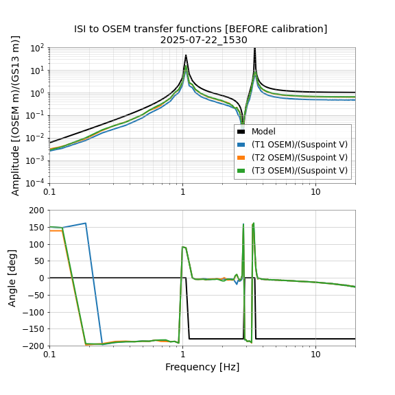
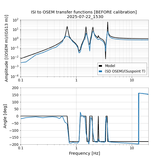
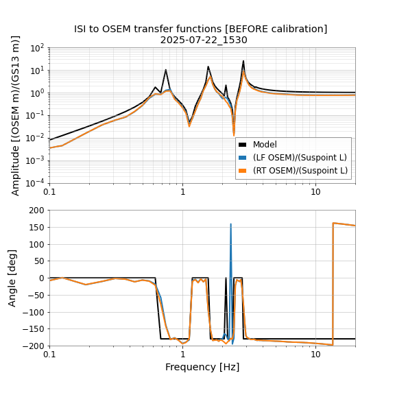
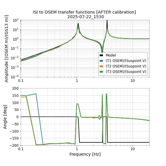
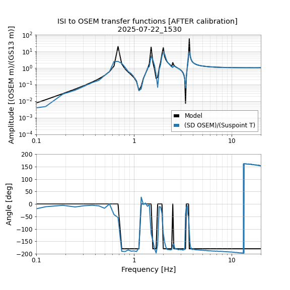
We have estimated a OSEM calibration of H1 SR3 M1 using HAM5 ST1 drives from 2025-05-21_0000 (UTC).
We fit the response M1_DAMP/HAM5_SUSPOINT between 5 and 15 Hz to get a calibration in [OSEM m]/[GS13 m]
This message was generated automatically by OSEM_calibration_SR3.py on 2025-07-22 16:24:05.000267+00:00 UTC
%%%%%%%%%%%%%%%%%%%%%%%%%%%%
EXTRA INFORMATION
The H1:SUS-SR3_M1_OSEMINF gains at the time of measurement were:
(old) T1: 1.478
(old) T2: 0.942
(old) T3: 0.952
(old) LF: 1.302
(old) RT: 1.087
(old) SD: 1.290
The matrix to convert from the old Euler dofs to the (calibrated) new Euler dofs is:
+0.74 -0.0 +0.0 -0.0 +0.0 -0.001
+0.0 +0.719 -0.0 +0.0 +0.0 -0.0
-0.0 +0.0 +0.545 -0.006 +0.0 +0.0
+0.0 +0.0 -1.209 +0.545 -0.003 -0.0
+0.0 +0.0 +0.18 -0.013 +0.629 -0.0
-0.148 +0.0 -0.0 +0.0 -0.0 +0.74
The matrix is used as (M) * (old EUL dof) = (new EUL dof)
The dof ordering is ('L', 'T', 'V', 'R', 'P', 'Y')
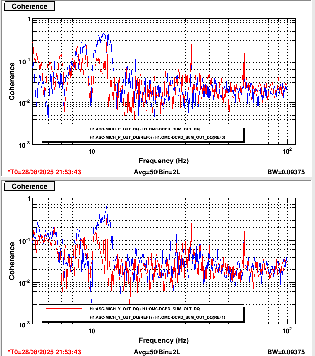
Please see the attached images of before calibrating and after calibrating.
Images attached to this report
Comments related to this report
Comparing these new OSEMINF gains to the gains we got last time we did this (84367) (before the satamp swap), they are pretty similar:
| OSEM | Previous Calculated OSEMINF gains (84367) | New Calculated OSEMINF gains (85907) | Percent difference (%) |
| T1 | 3.627 | 3.213 | 12.1 |
| T2 | 1.396 | 1.517 | 8.3 |
| T3 | 1.345 | 1.494 | 10.4 |
| LF | 1.719 | 1.733 | 0.8 |
| RT | 1.490 | 1.494 | 0.2 |
| SD | 1.781 | 1.793 | 0.6 |
So that's another indicator that the sat amp swap did not have much of an effect on the suspension response to suspoint excitations
The calibration values posted here are correct, but the theoretical alignment values are incorrect. See the corrected post from Sep 26th, 2025.
[CORRECTED LOGPOST LHO: 87162]