HAM2-3 work today (Cheryl, Ed, Sheila, Betsy)
Since Sheila and I finished after the rest of the crew I'll post this log, but hope that Cheryl (or other 2) feel free to add.
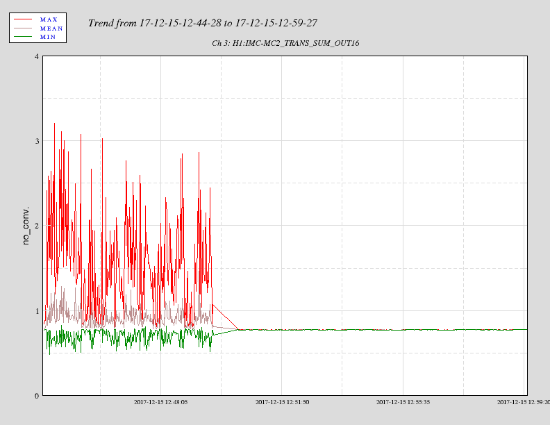
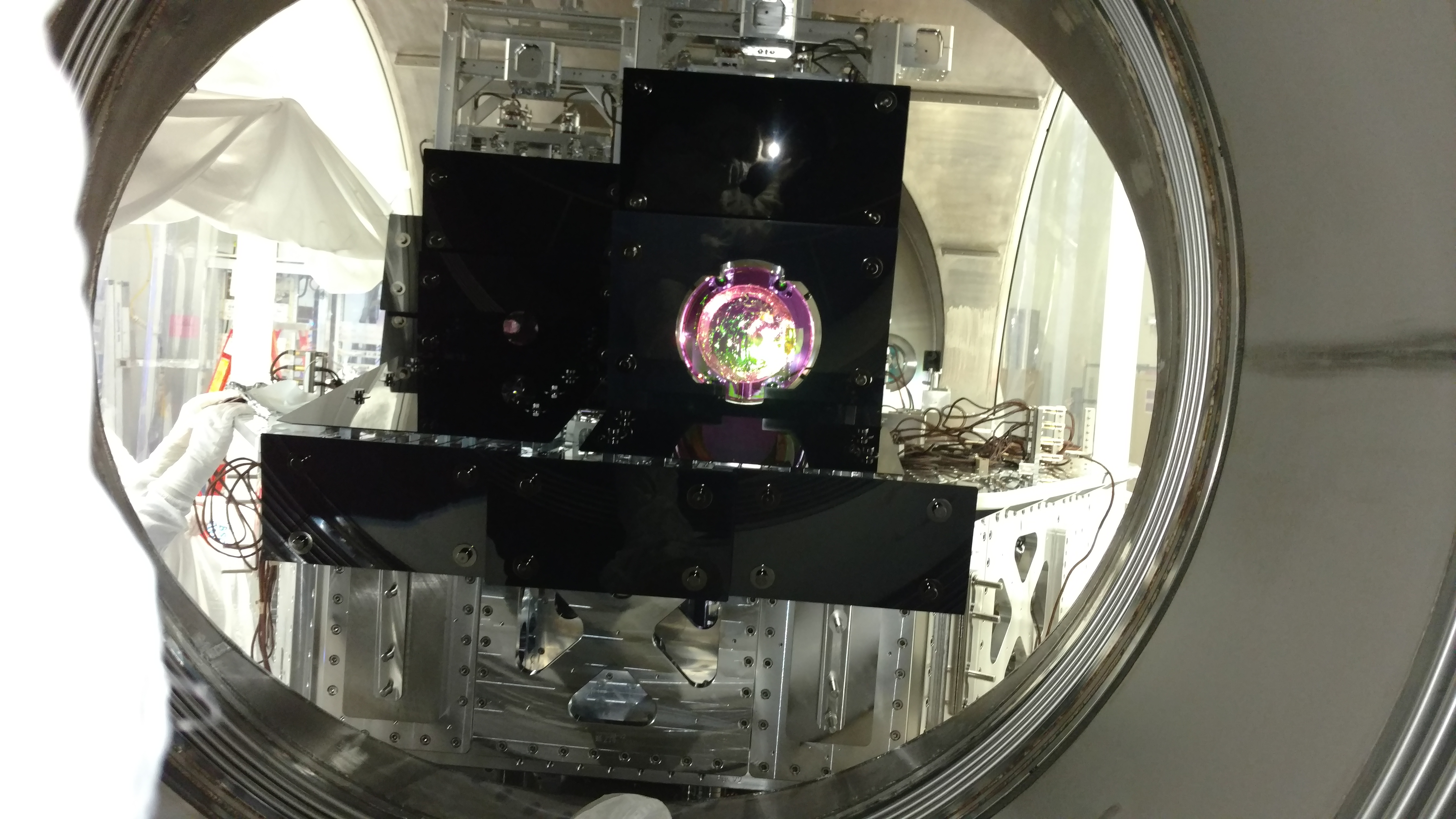
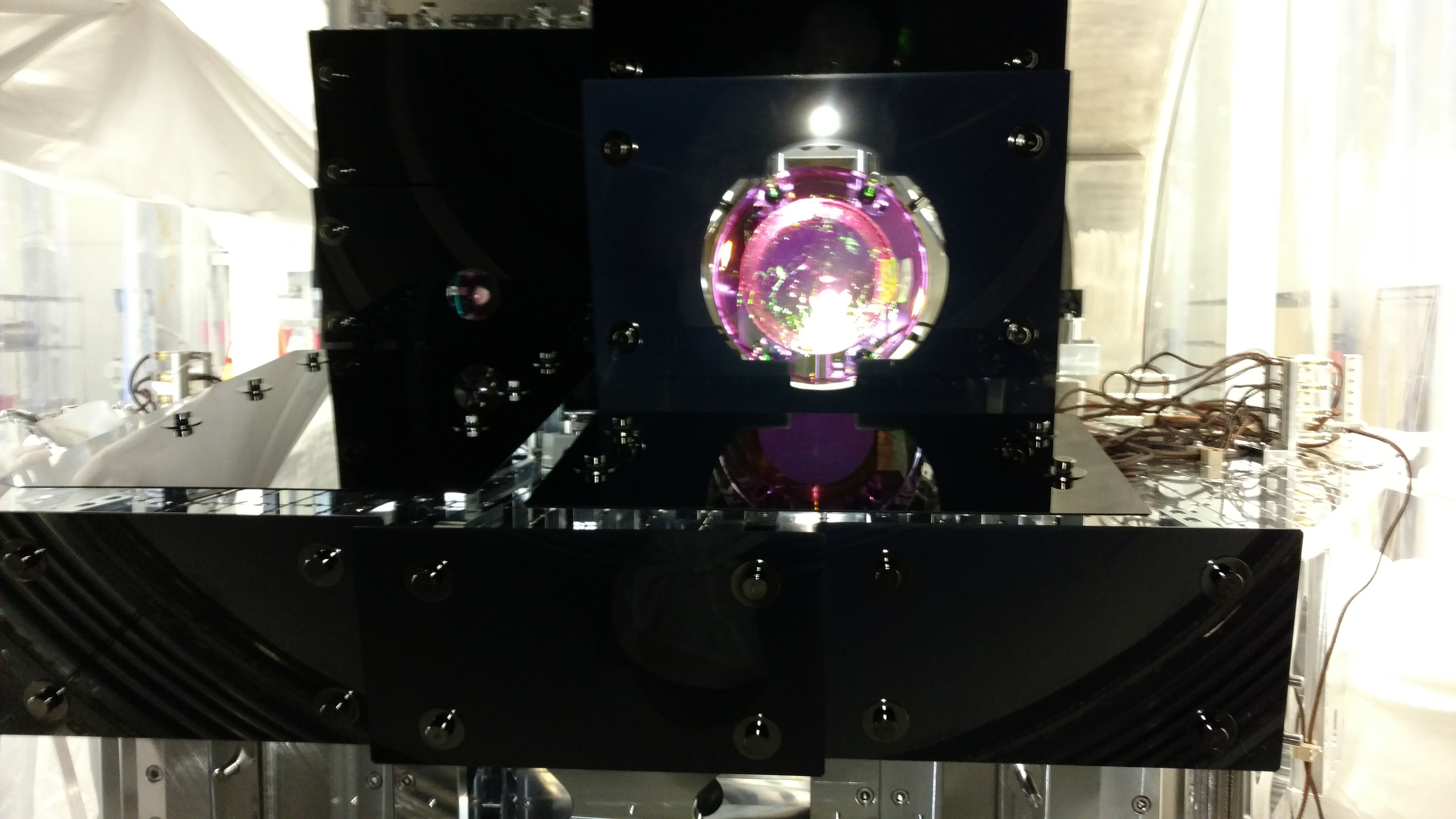
After some whiteboard work this morning to interpret the misalignments that Cheryl reported at IM1 yesterday, we proceeded with walking the beam through the IMs, adjusting mechanical yaw and pitch along the way. Although only mostly sure, we think the misalignment of IMs reported yesterday were due to the gamut of mechanical adjustments made to them over the last few weeks (a few bolt tightening exercises, B&K knocking, realignments within the cage, slight misalignments left over from previous alignments, you name it...). So we decided that it was not crazy to think that twisting the tower to correct such things in order to buy back maxed AOSEM ranges was prudent. In the end, the twist of IM1 to IM2 was achieved by loosening dog clamps and barely applying some finger pressure to the tower to 'feel' a sub-millimeter slide on the table". We needed even less at IM3 and IM4 in yaw, and nothing at IM2. Only IM4 needed additional Pitch mechanical bias relief, for this Cheryl needed to remove the structure baffle and switch the pitch adjusting locking collar to the back side for ease of use. At COB just now, we have reasonable bias on all IMs (~50% DAC range used here and there), and the beam well centered on all, plus the input of the FI, the output of the FI, the PRM iris, the PR2 iris, and the PRM refl beam going back to HAM1 (with exisiting bias from previous alignment).
For the record, to do this we:
Translated IM1 to center beam on closes wave plate and baffle,
Yaw/Pitch IM1 to center beam on IM2 and fine align to FI input,
Yaw/Pitch IM2 to center output of FI and check alignment ot IM3 is also good,
Yaw/Pitch IM3 to PRM iris,
Yaw/Pitch IM4 to PR2 iris,
Bias relief mechanically as needed,
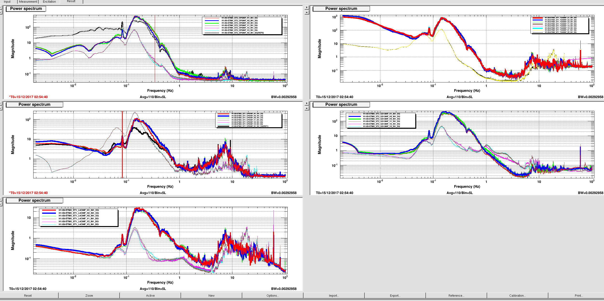
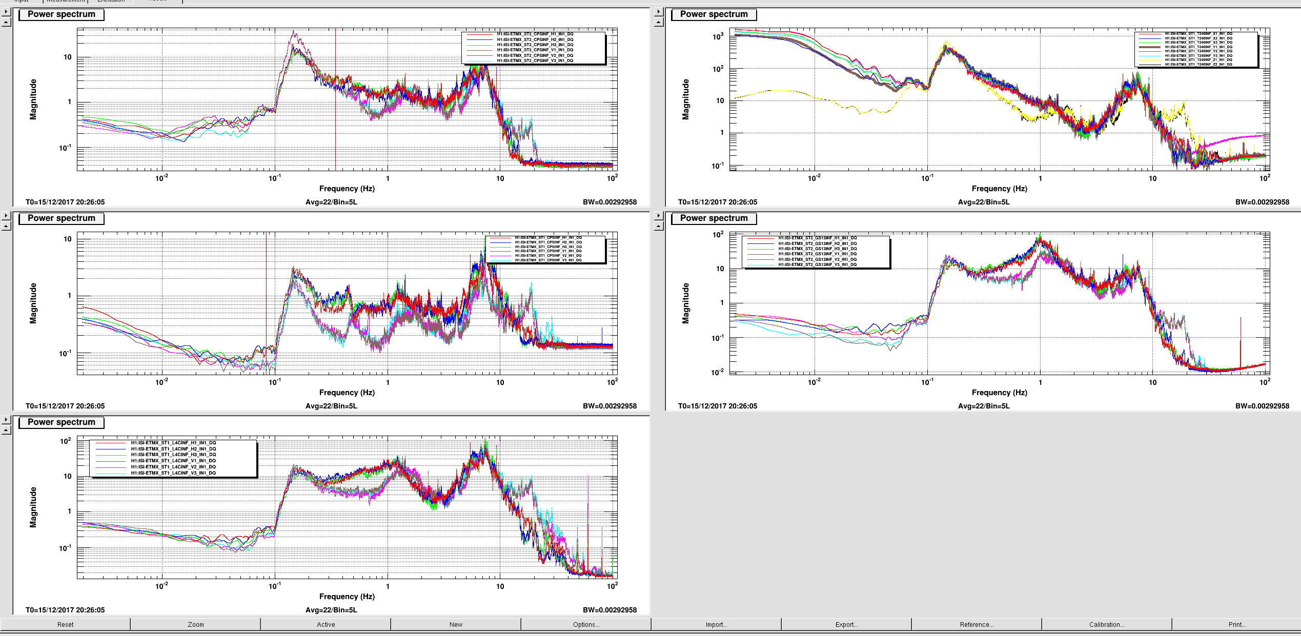
Took quick TFs along the way to make sure IMs were healthy as we went since we were adjusting things on them,
Centered IM3 LR and UR AOSEMs since 1 had become near 0 and the other was also slightly out and was super easy to fix.
I also fixed that PRM front dummy flag that Cheryl reported as getting knocked during cleaning the other day. All AOSEM signals look good on that guy.
MONDAY - Install bypass mirror and align ISS.