marc.pirello@LIGO.ORG - posted 13:39, Tuesday 21 November 2017 - last comment - 17:20, Tuesday 21 November 2017(39497)
Fixed Bullseye PD signal chain
Richard M, Dave B, Fil C, Peter K, Marc P.
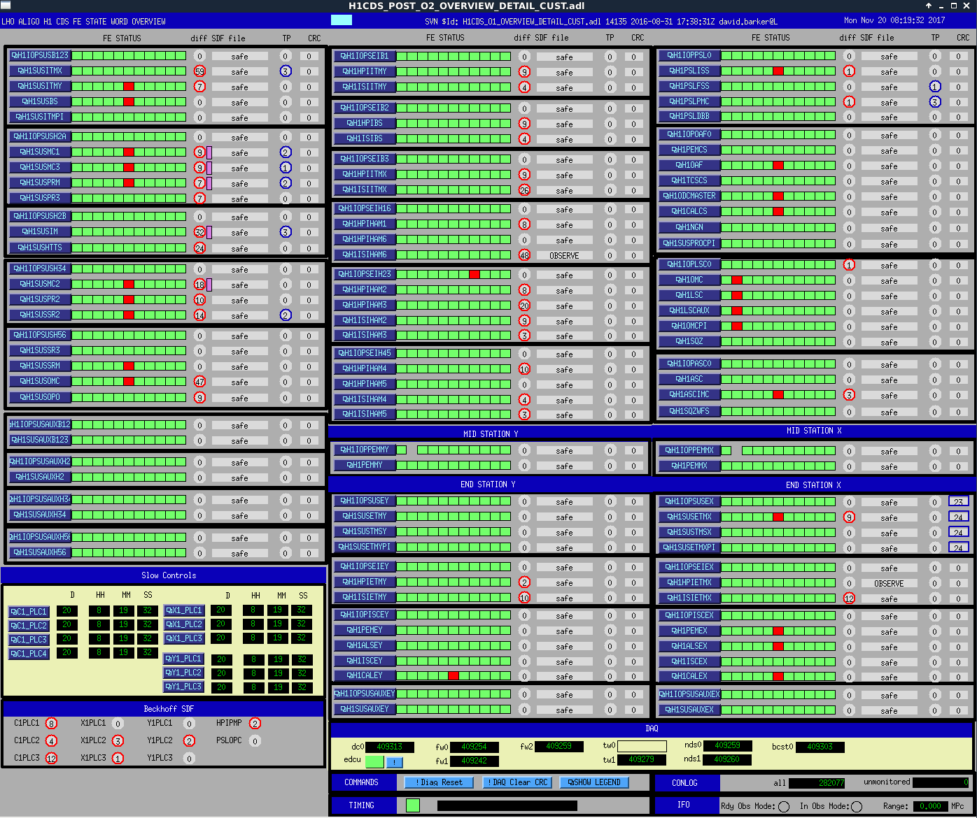
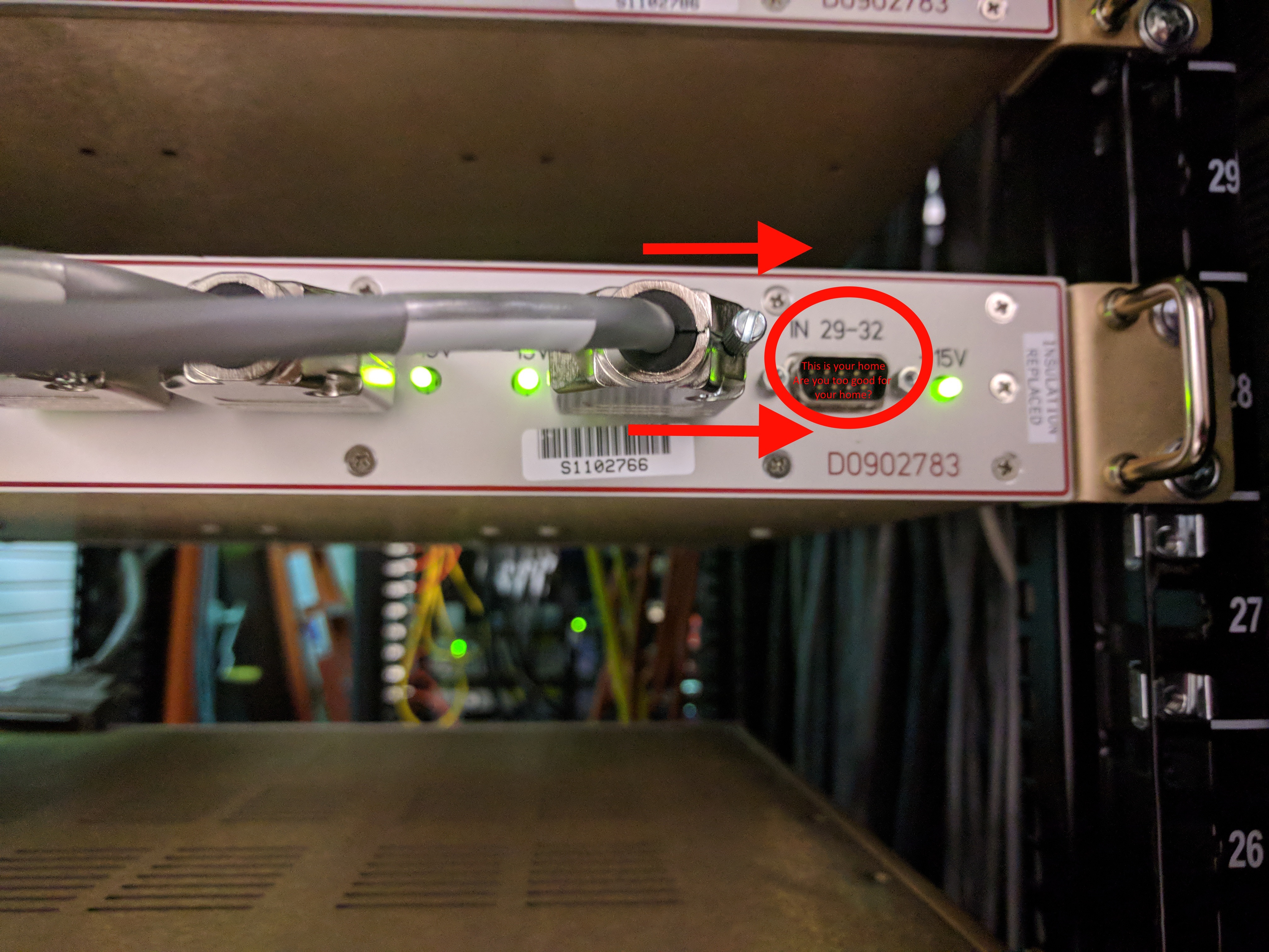
This morning we completed an investigation of the Bullseye PD signal chain. It was determined that the ISC250 cable position in AA Chassis S1102766 was incorrectly placed one space to the left and should be attached to (IN 29-32). This was likely overlooked when these chassis were rearranged to make space for squeezer electronics on November 2nd, . The cable was moved to the correct position and we verified that the signals are received by the ADC.
Images attached to this report
Comments related to this report
T1100472 would indicate that the cable was correct, but not the model.