I wanted to get a quick summary of events on this spacer, but if I missed something or have something wrong please let me know.
On Friday, Keita and Sheila were aligning HAM5 and noticed that the beam height was odd going to ZM2. Jeff Kissel was consulted and he looked up drawings and found a possible discrepancy in the beam height. Some emails were exchanged with Lee McCuller and Koji, and in the mean time Keita, Sheila, Gerardo, and I talked to Lisa and Calum on TeamSpeak. Turns out that the spacer that sits under the ZM2 tip tilt (D1600005) was 0.76" too tall. Sheila and I measured in chamber and confirmed this (alog39477). This height difference comes from the difference in beam height on HAM5 between L1 & H1. Our two options:
a) Remove 0.76" from the spacer height and then clean, rebake, and reinstall.
- There was not enough material to remove from the bottom, and the top would need some holes drilled and tapped, then vent holes drilled on the sides. Modifying the top would create a higher contamination risk but seemed like easiest way to modify this. To speed up the process, we would need an approval on a waiver to allow a truncated version of cleaning and baking.
b) Deal with the height difference and try to move on with alignment.
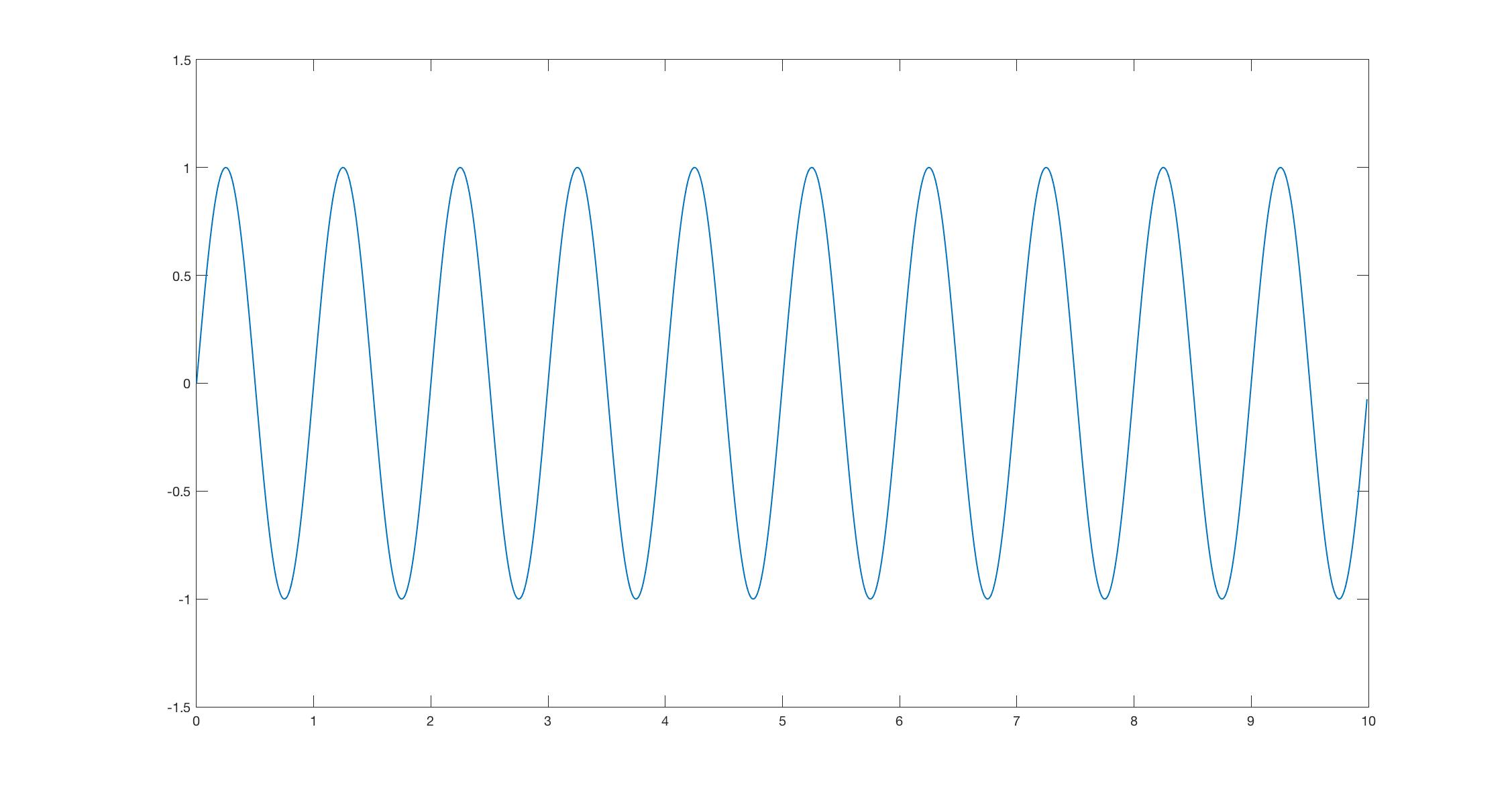
- This was the ugly option because after we align the beam to ZM2, we are going to shoot it into HAM6 and through two iris's that will remain until the VIP is installed. The irises are nominally 4" off the HAM6 table, but with the ZM2 up 0.76" they would need to be raised up slightly. Finding correctly sized posts and making adjustments would be a pain. The other issue with this option is there was potential for loss due to the polarization change in the changing height. Keita did the matlab math (alog39478) and it turns out that it wouldn't be an issue, but the ugly alignment doesn't go away.
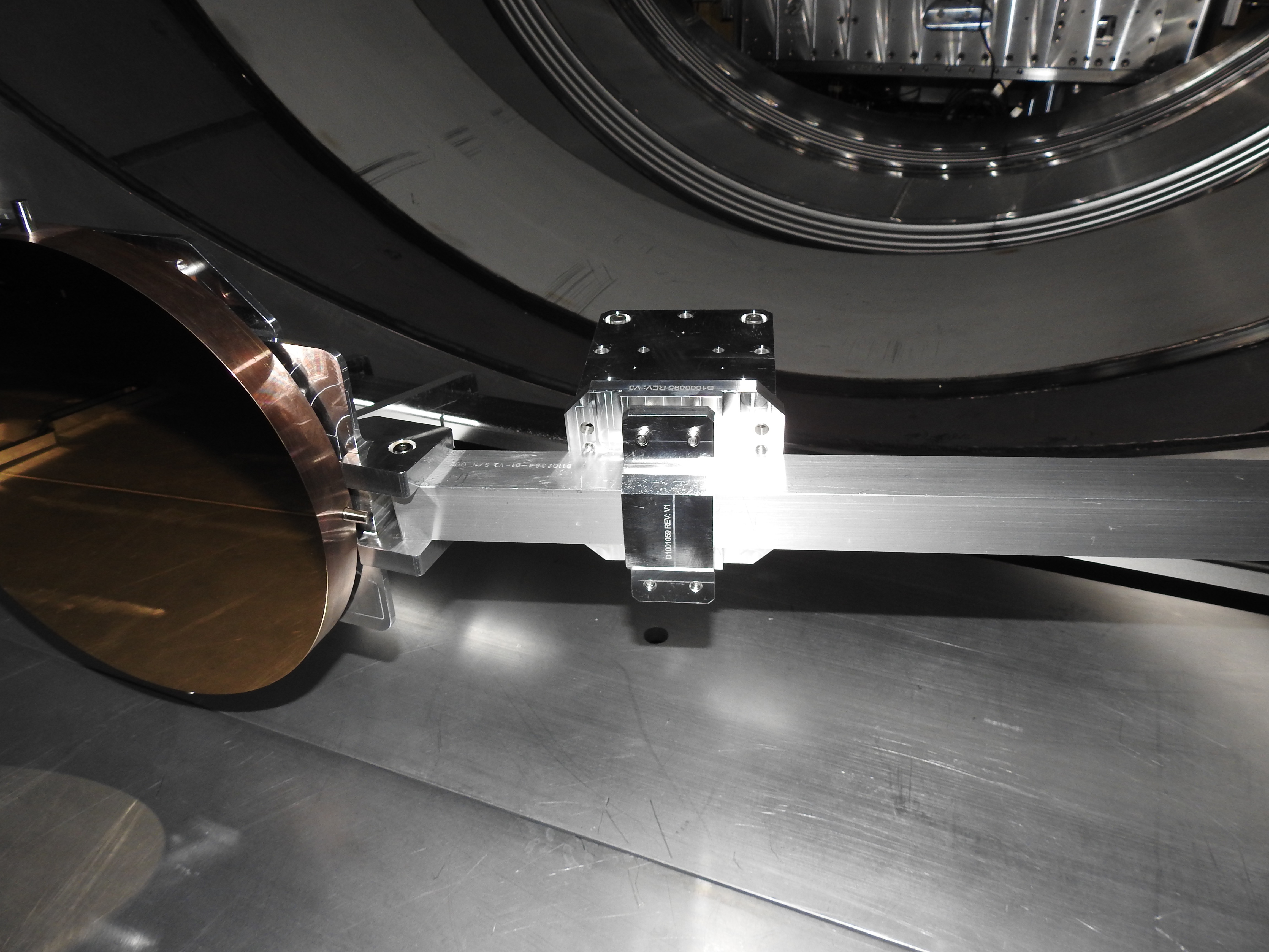
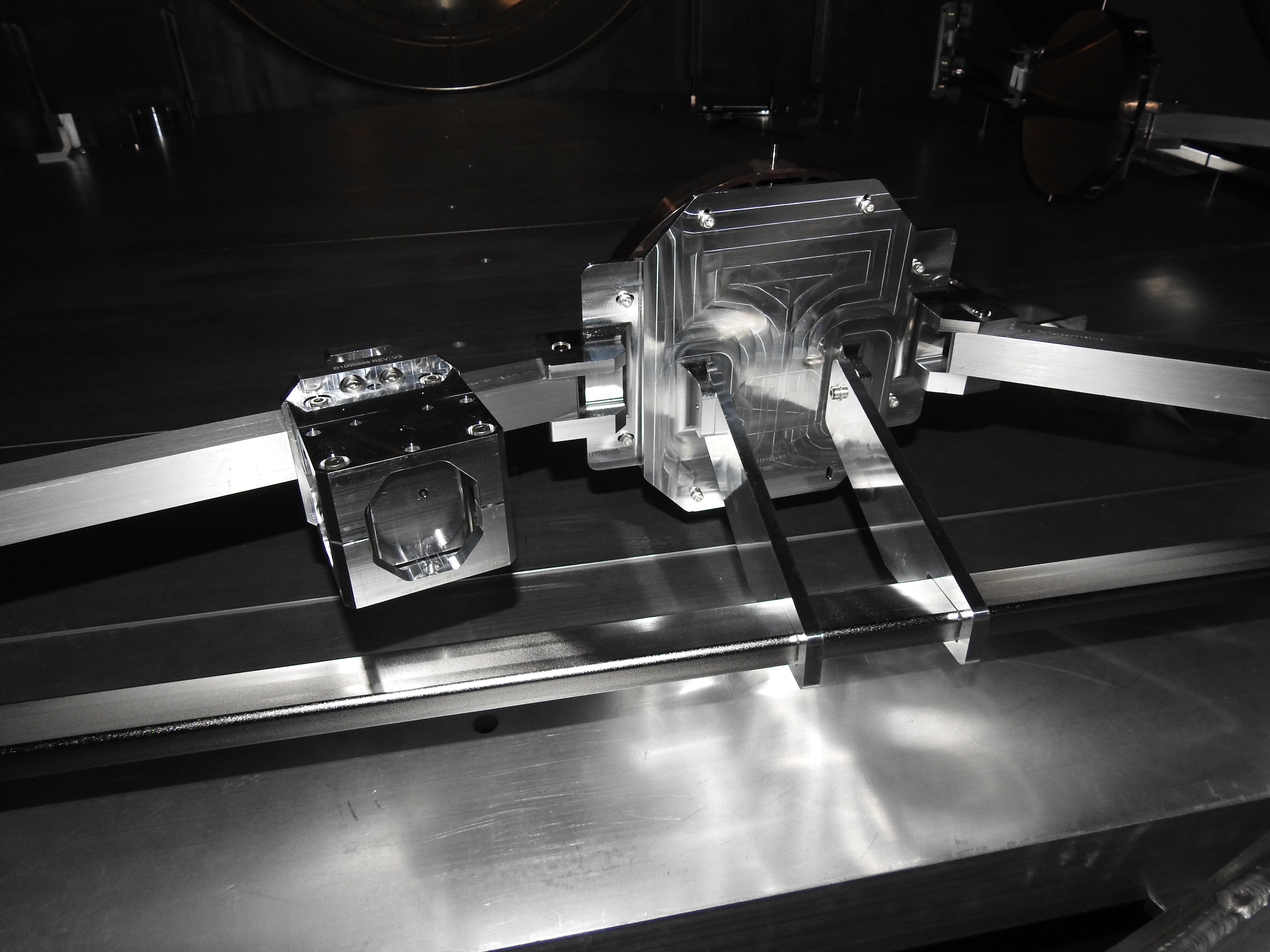
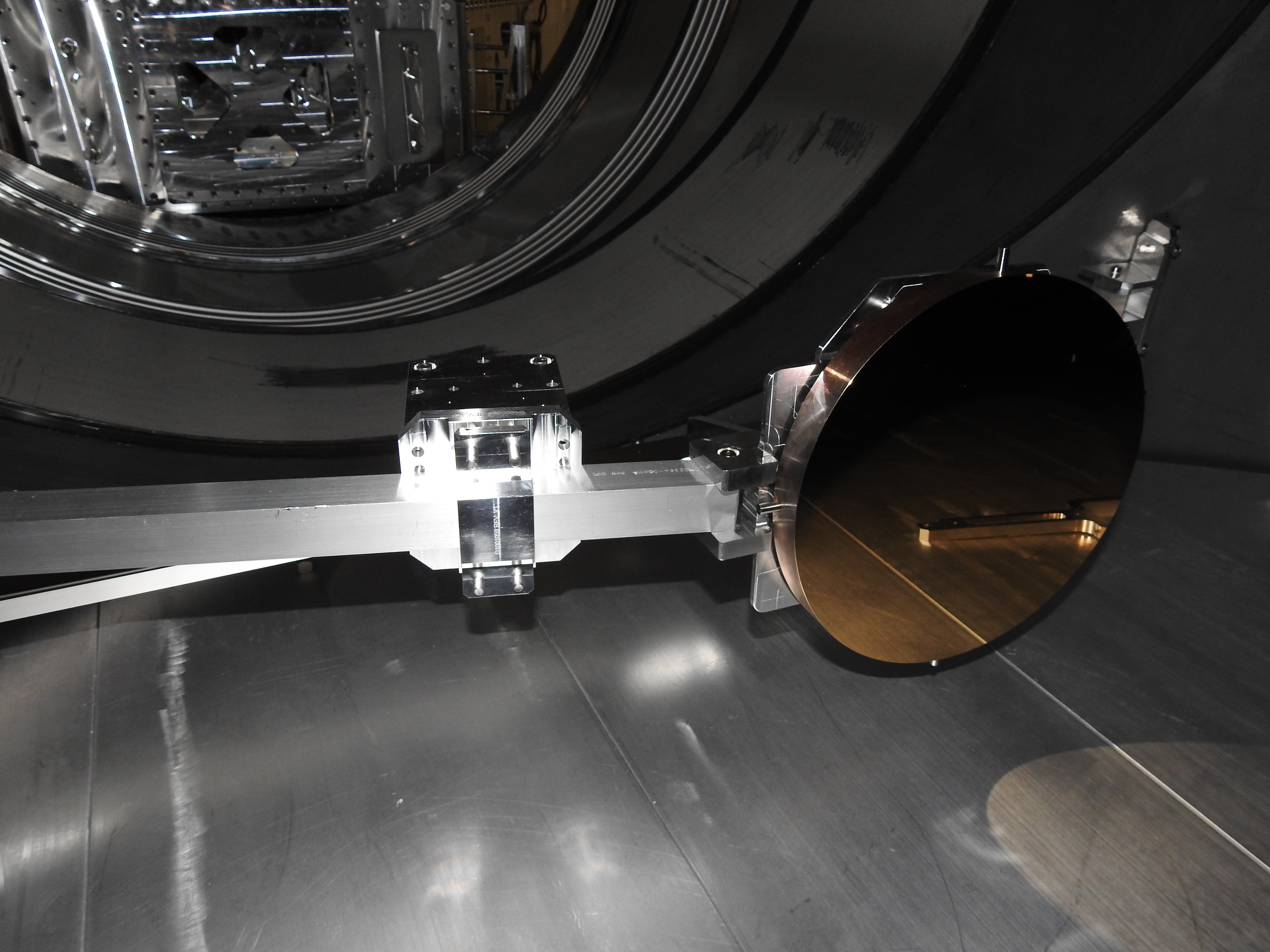
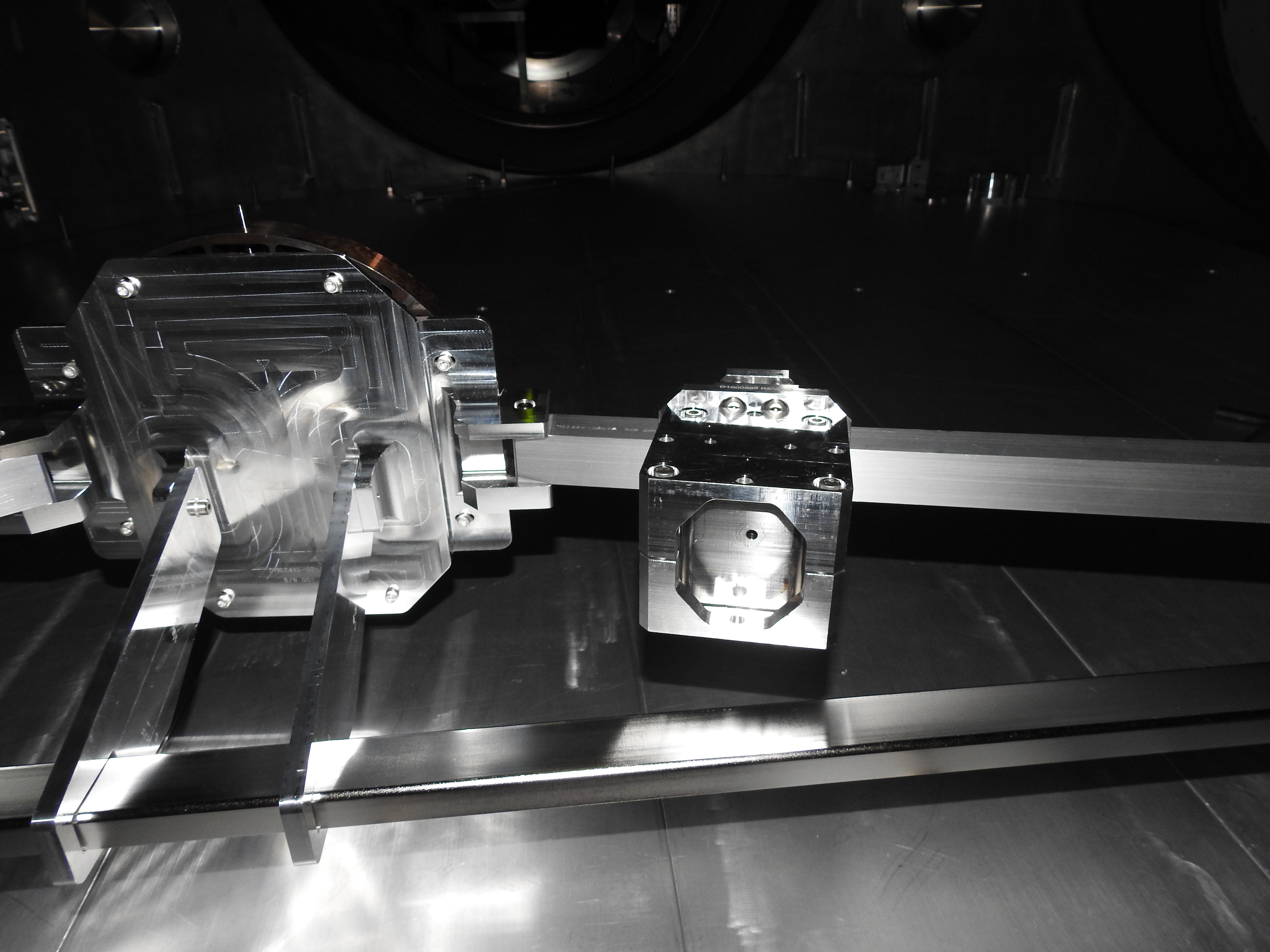
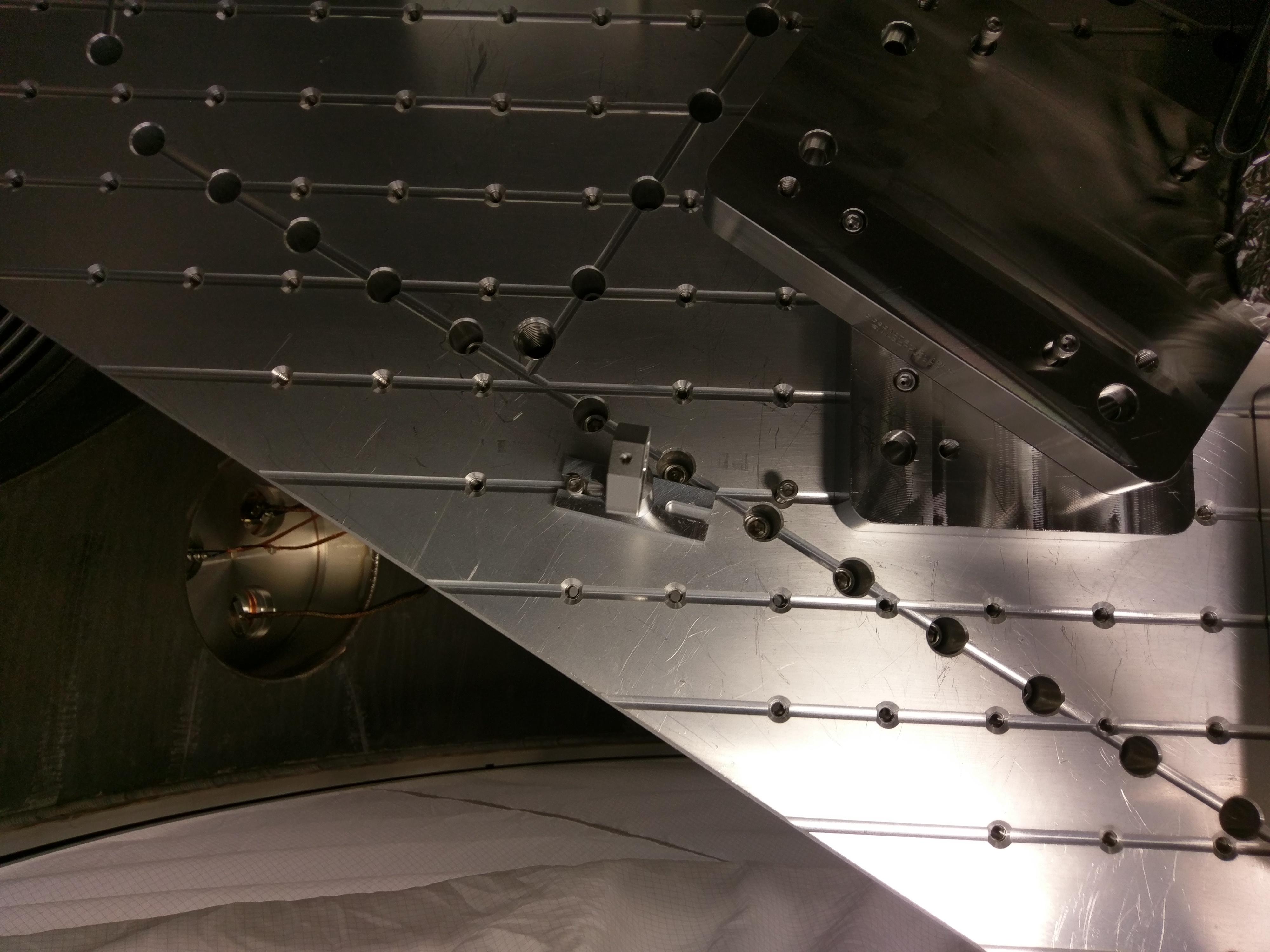
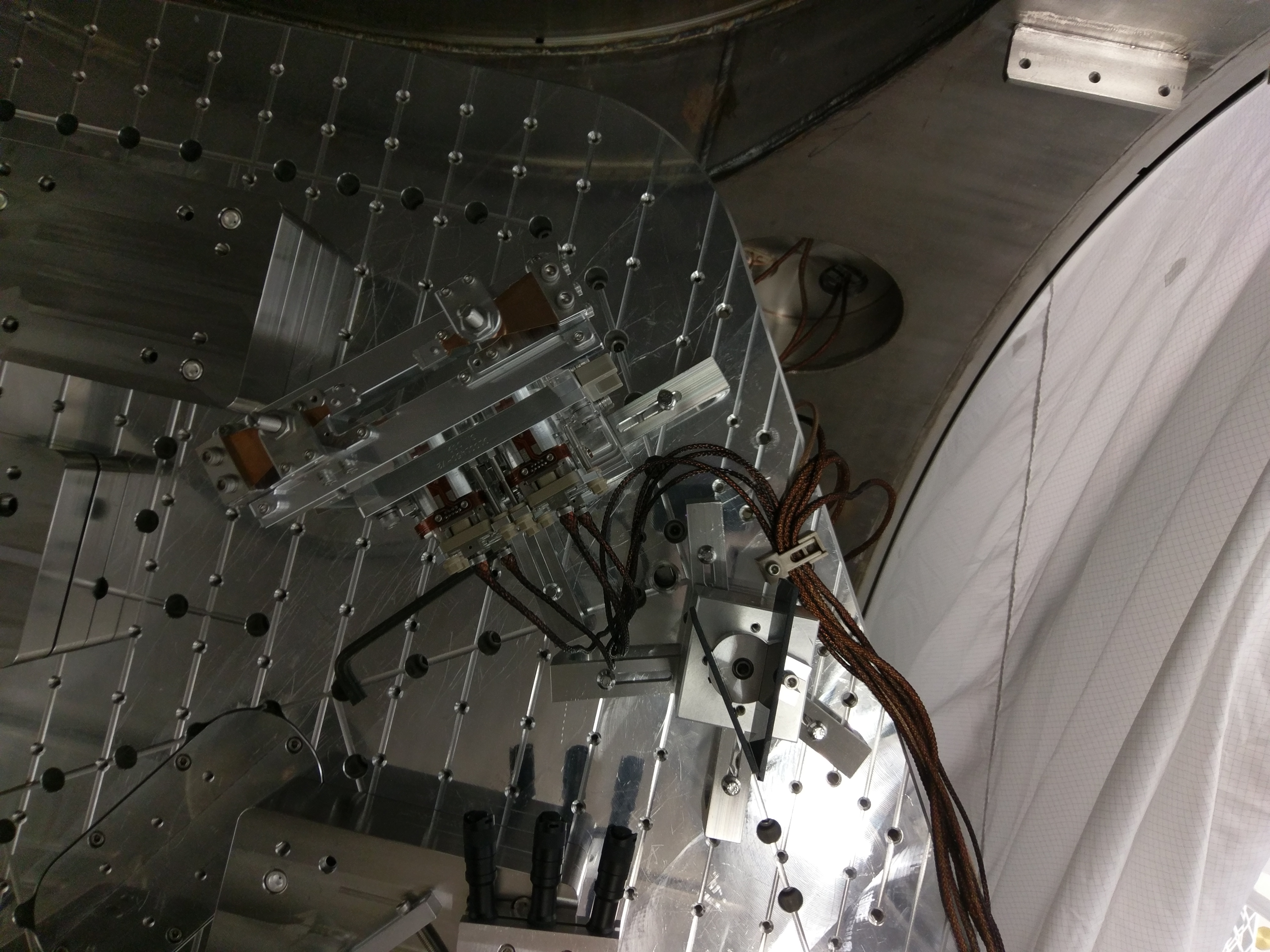
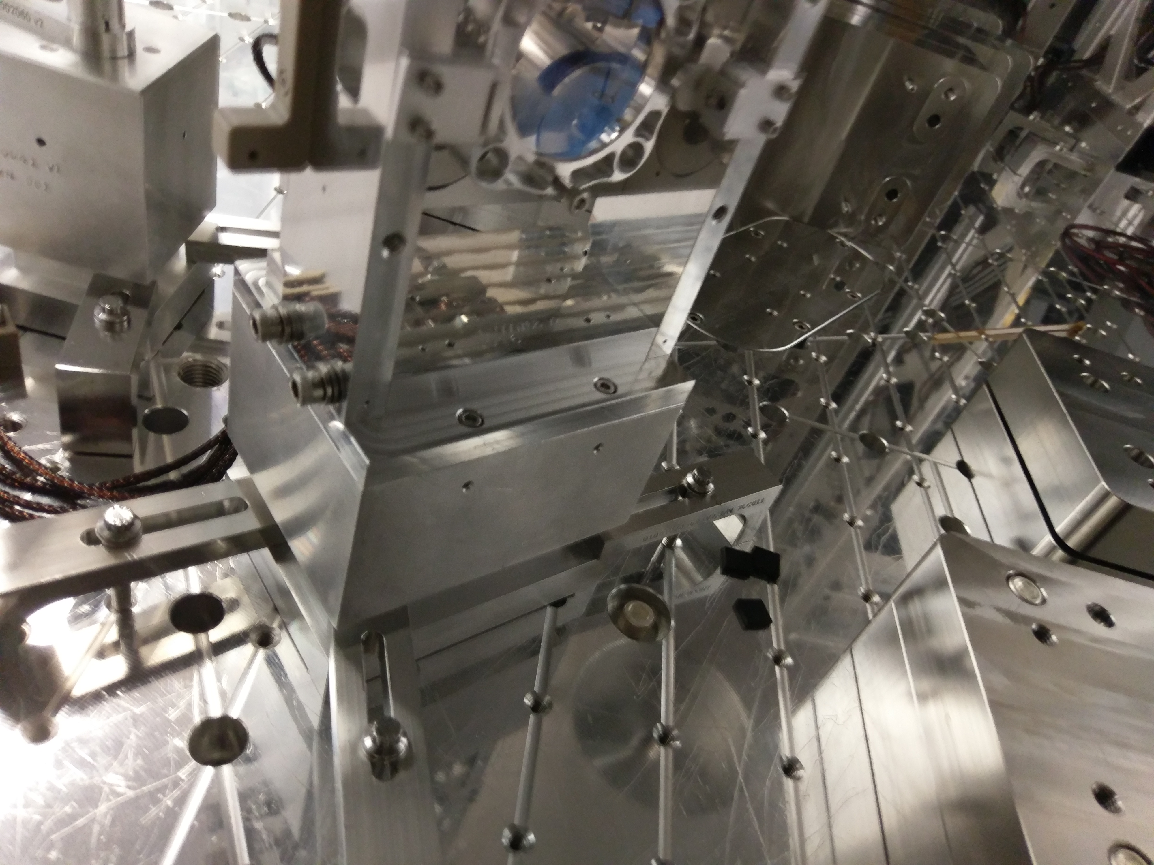
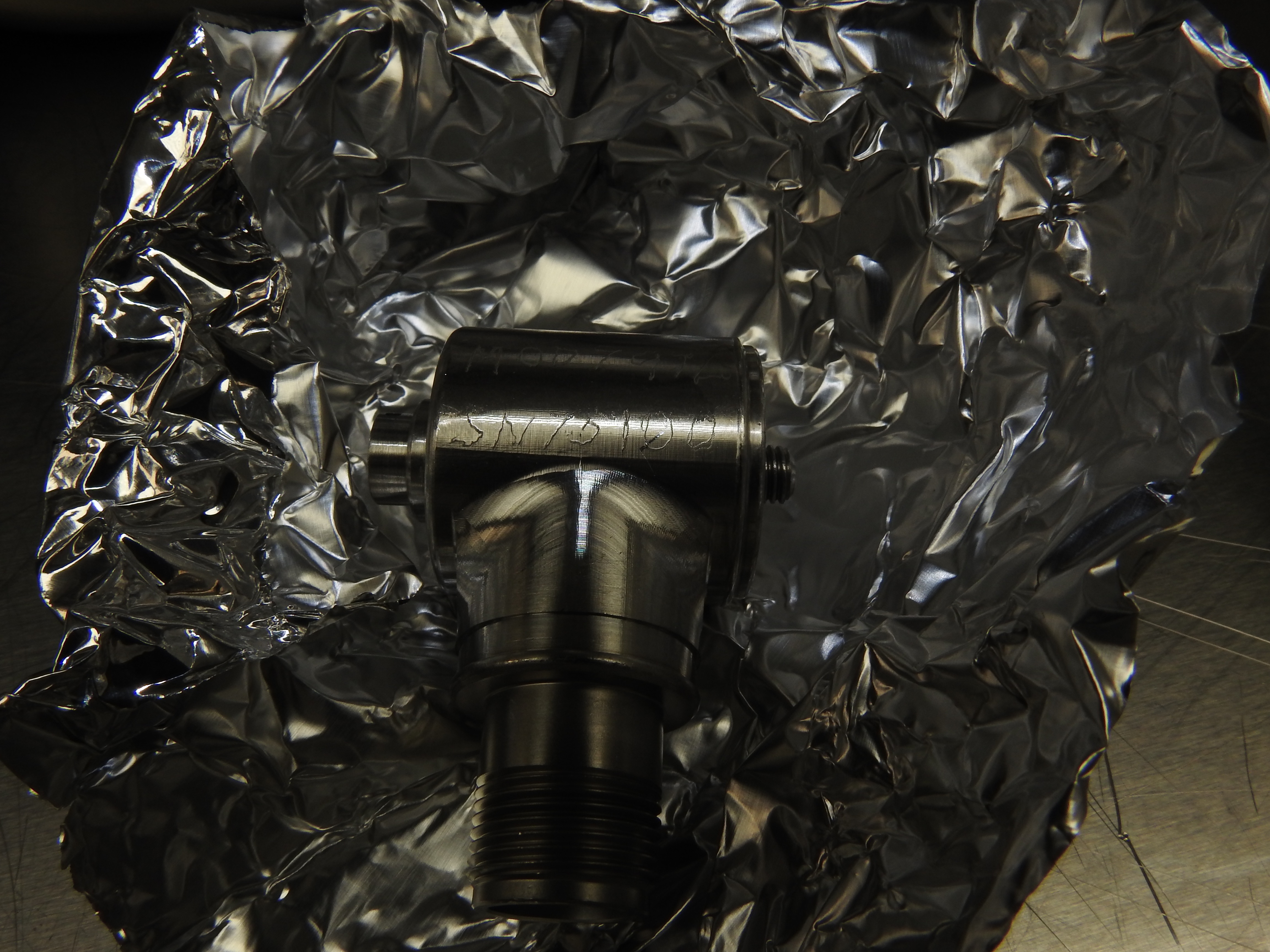
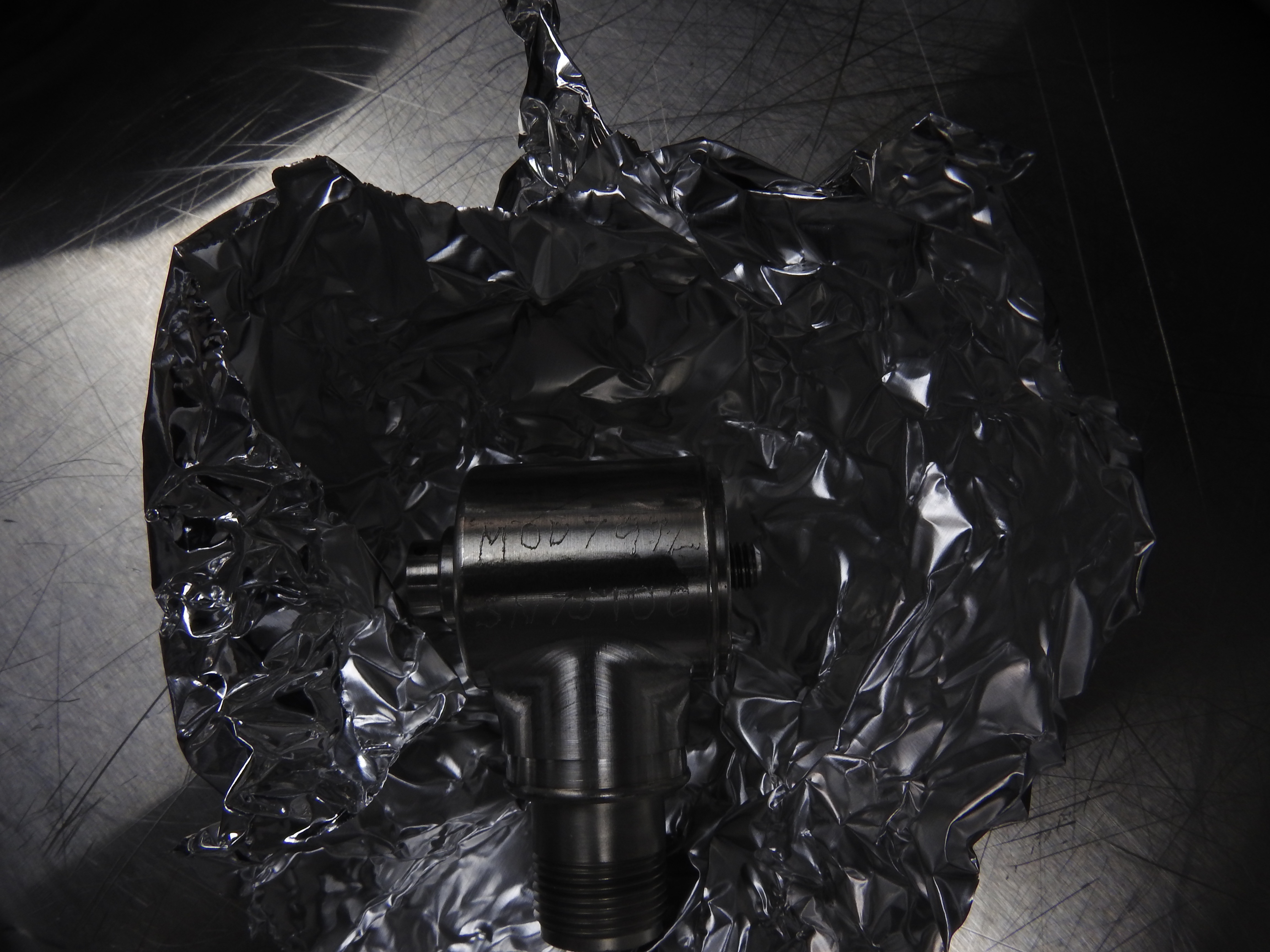
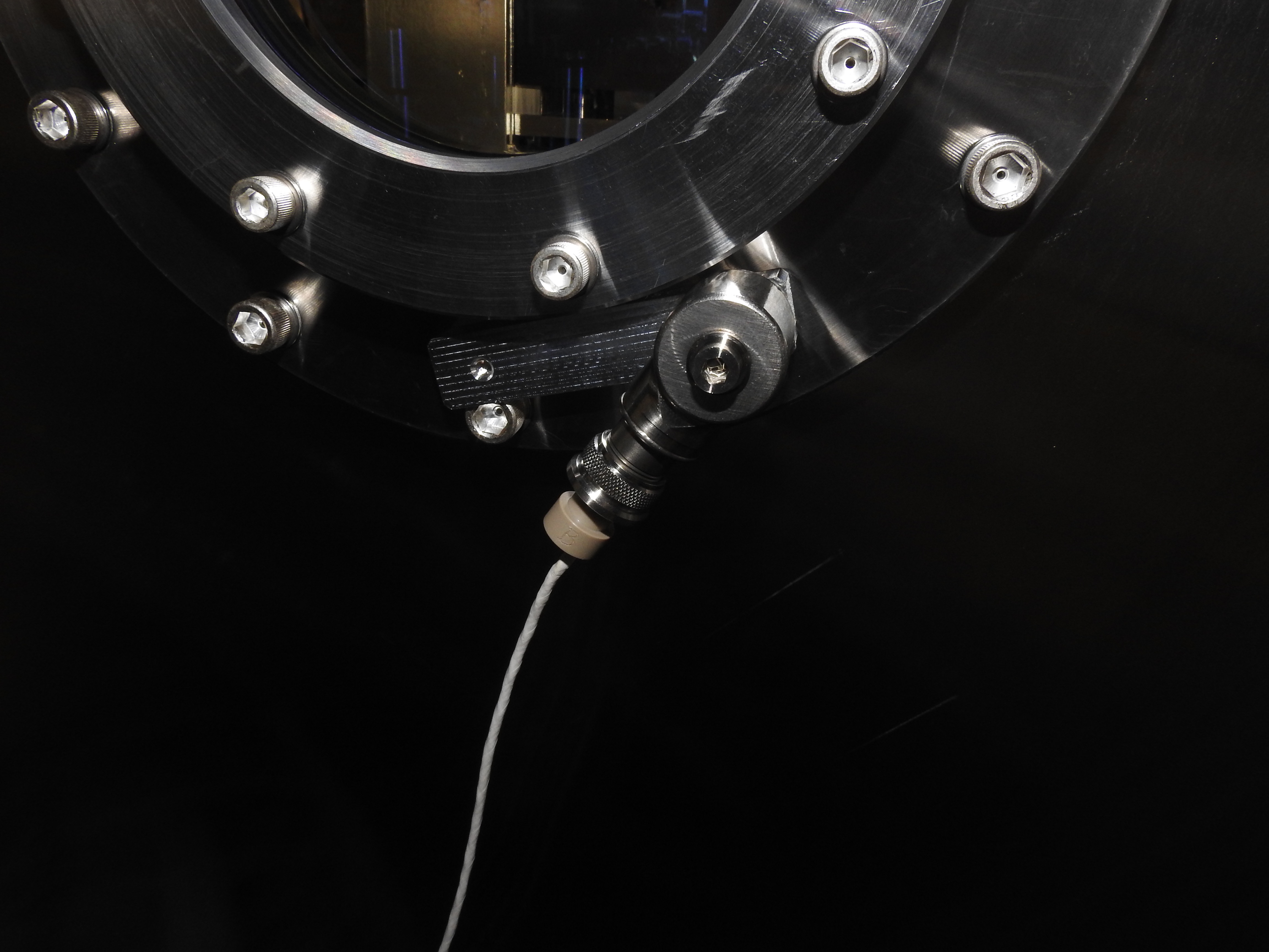
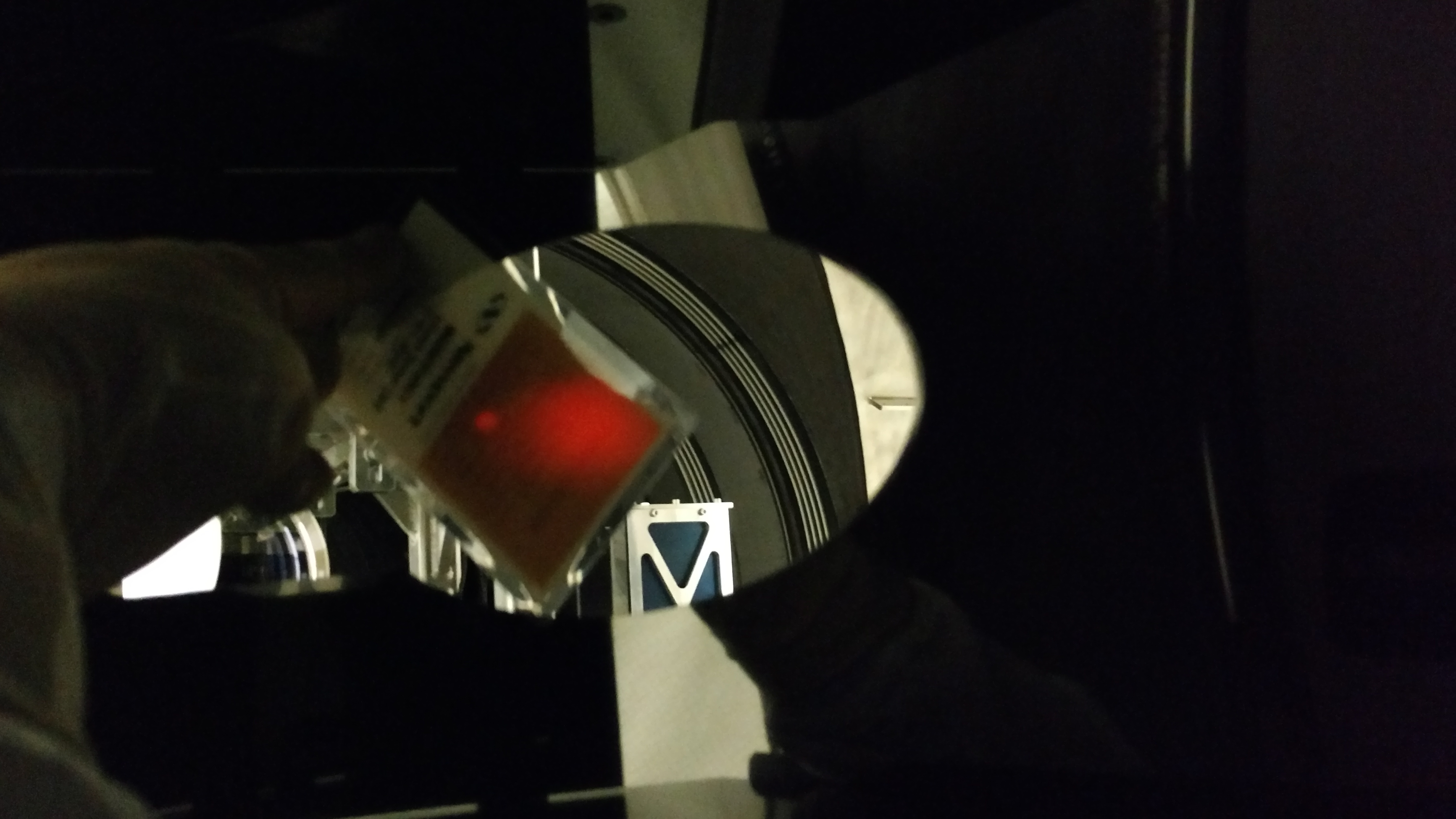
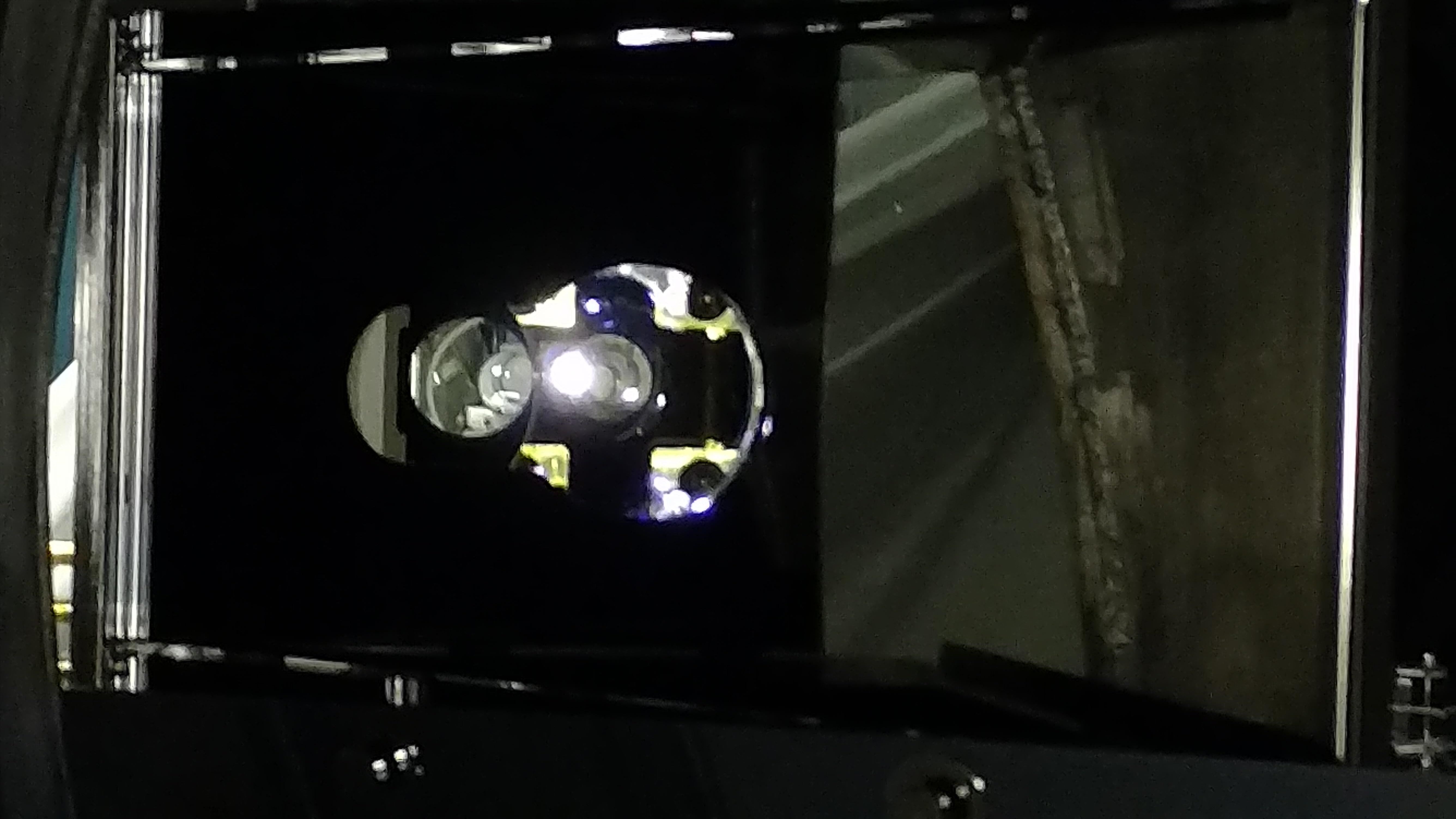
It was decided to chop the top (option a) and on Monday I pulled out the spacer, handed it off to Tyler to machine, and then he gave it to Chris for a clean and 12hr air bake. Yesterday, I reinstalled the spacer and aligned ZM2 to the coordinate drawing. Keita, Sheila, and I aligned the beam from the OFI to ZM2 in pitch and will do more with yaw either today or Monday after the holiday. Pictures attached to show height difference. For reference the spacer under the beam dump is what the TT spacer used to be.
Aside: the beam dump also sits on a spacer that is 0.76" too tall. This was an easy fix of just getting a slightly smaller post, so it wasn't the main character of this story.