[Jenne,Sheila,Corey,Vaishali]
Summary : We are reliably locking to NLN (If I remember correctly ~62 MPc)
Timelapse of the locking sequence :
1. Problem : IFO losing lock at Reduce modulation depth.
Solution : We started tackling the problem by first undoing the offsets on the POP_WFS_A in order to try an help our recycling gain which had tanked from its normal value of about 30 ish to 26. We could only bring this upto 28 by undoing the offsets that Sheila added yesterday (see alog 36686).
- Lost lock here once by clicking on Noise tunings
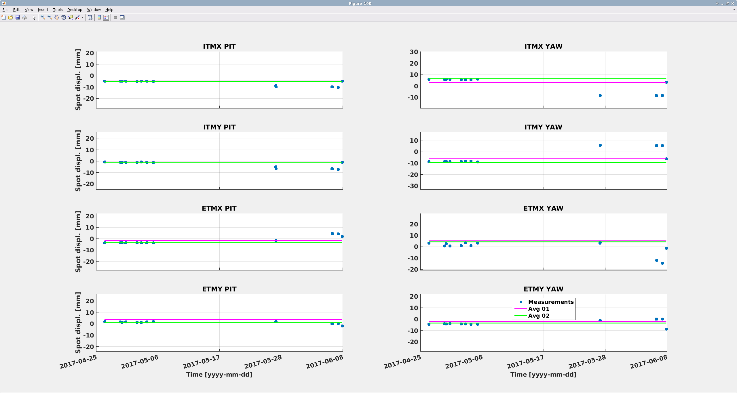
2. Problem : Jenne then noticed that the spots had moved a rather large amount (~2 cm on the ETMs in Yaw and ~1 cm in Pitch). See attached figure (SpotPos_O1O2) which shows the average spot position on the ITMs and ETMs for O1 in pink and O2 in green.
Solution : We changed the L2A decoupling coefficients and set them to what they were before the vent by using dither lines frequencies that were in the a2L script. The logic behind doing this was to try and improve the beam pointing into IFO and bring up the PRC Gain (which is now sitting at ~30) .
- Lost lock here once because we used very large steps for moving the spots
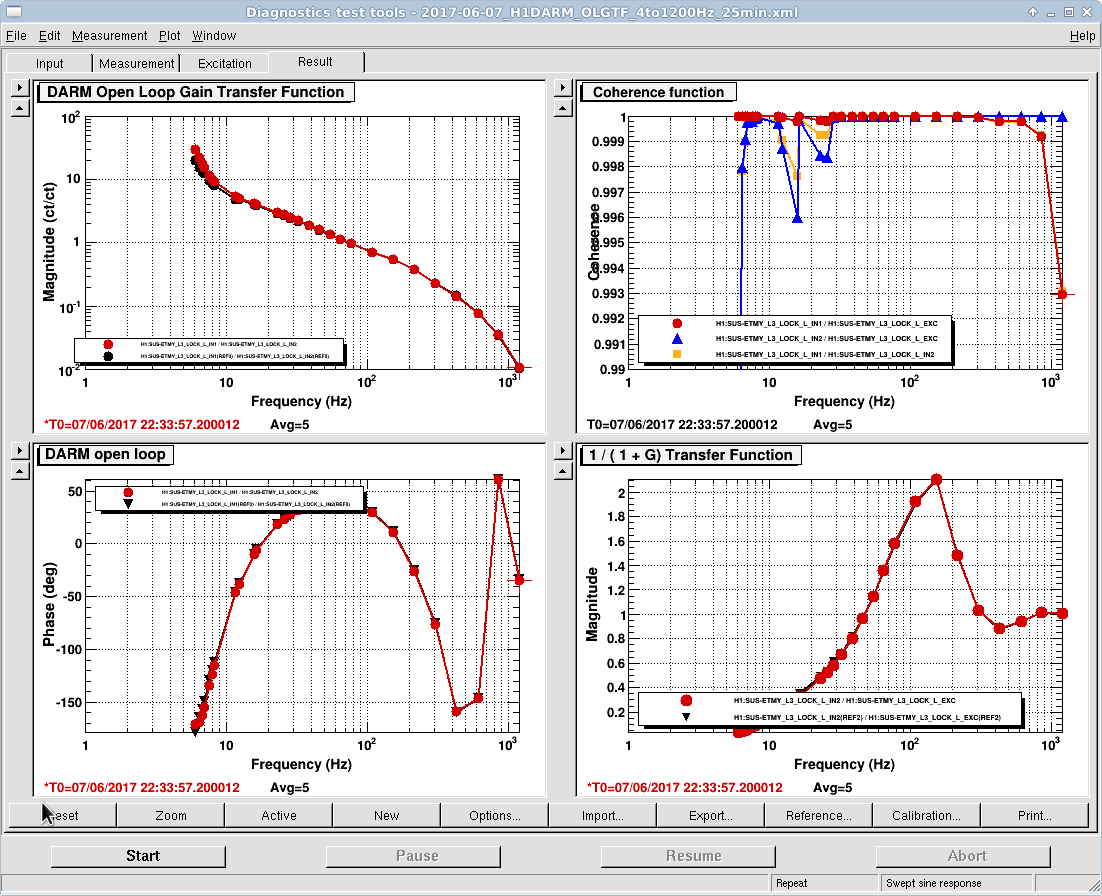
Logic/Methodology : This 'reverse a2L' where we moved PR3 in Pitch and Yaw (separately keeping an eye on the recycling gain and using that as a figure of merit) to affect the spot position on the ITMs and added an offset to CSOFT and DSOFT in combination to move the spot on the ETMs is basically us trying to move the actuation node to the beam spot (a2L moves actuation node to beam spot). We compared the dither lines showing up in a current calibrated DARM spectra to the an old calibrated DARM spectra reference and slowly changed the L2A decoupling coefficients in both pitch and yaw. All of this process was done in the guardian state PR3 spot move.
3. We reset the POP_WFS_A PIT and YAW again .
4. Problem : SRCL Feedforward filters different than before
Attempted solution : reset all the filters on the SRC Feedforward to what they were at the beginning of O2.
Consequence : This however didn't work too well and we went back the filters that Sheila had chosen in the alog 36686.
5. Jenne has also reset the green initial alignment set points, so hopefully the next initial alignment will come back to the place we left it thus making relocking easier.
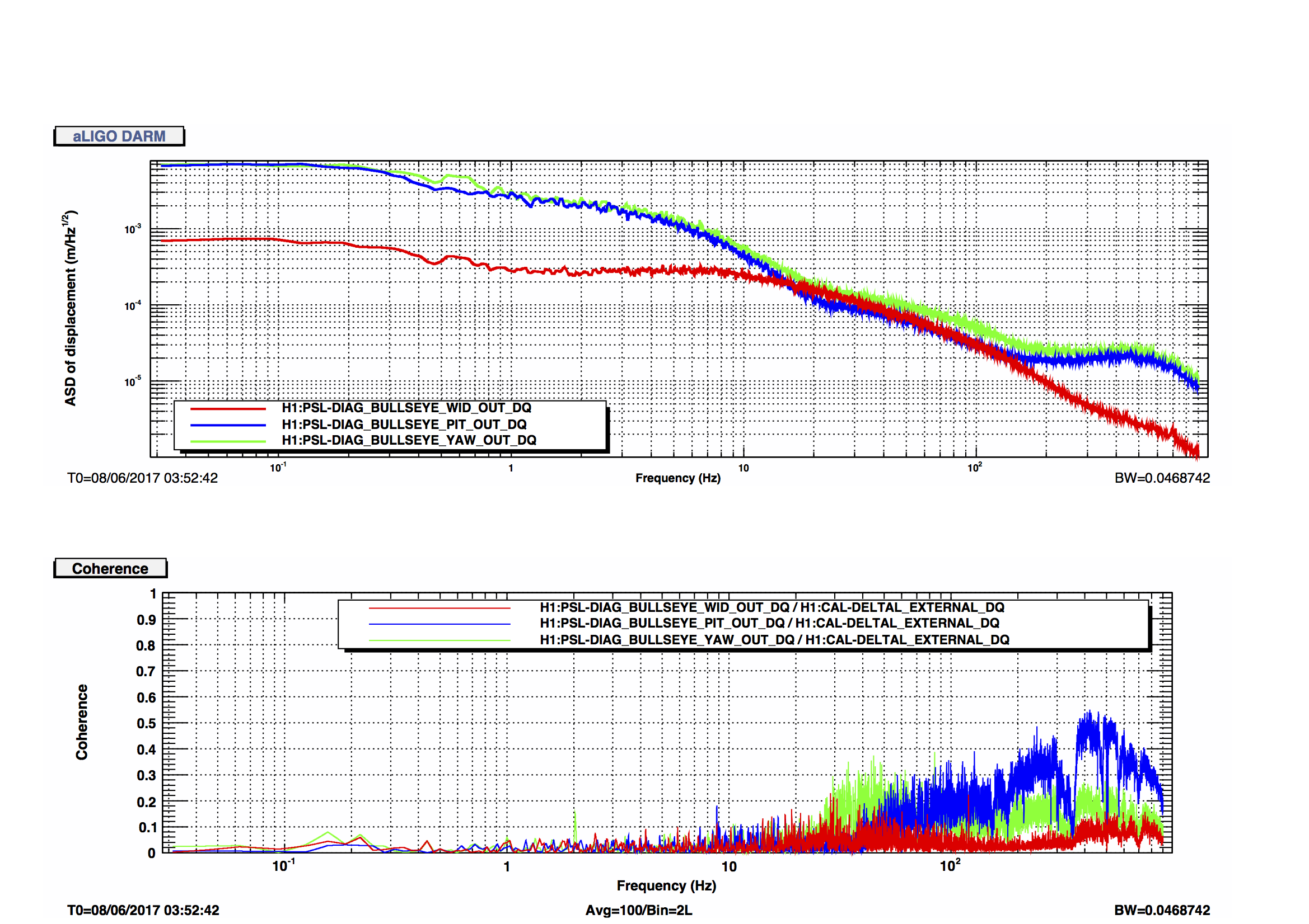
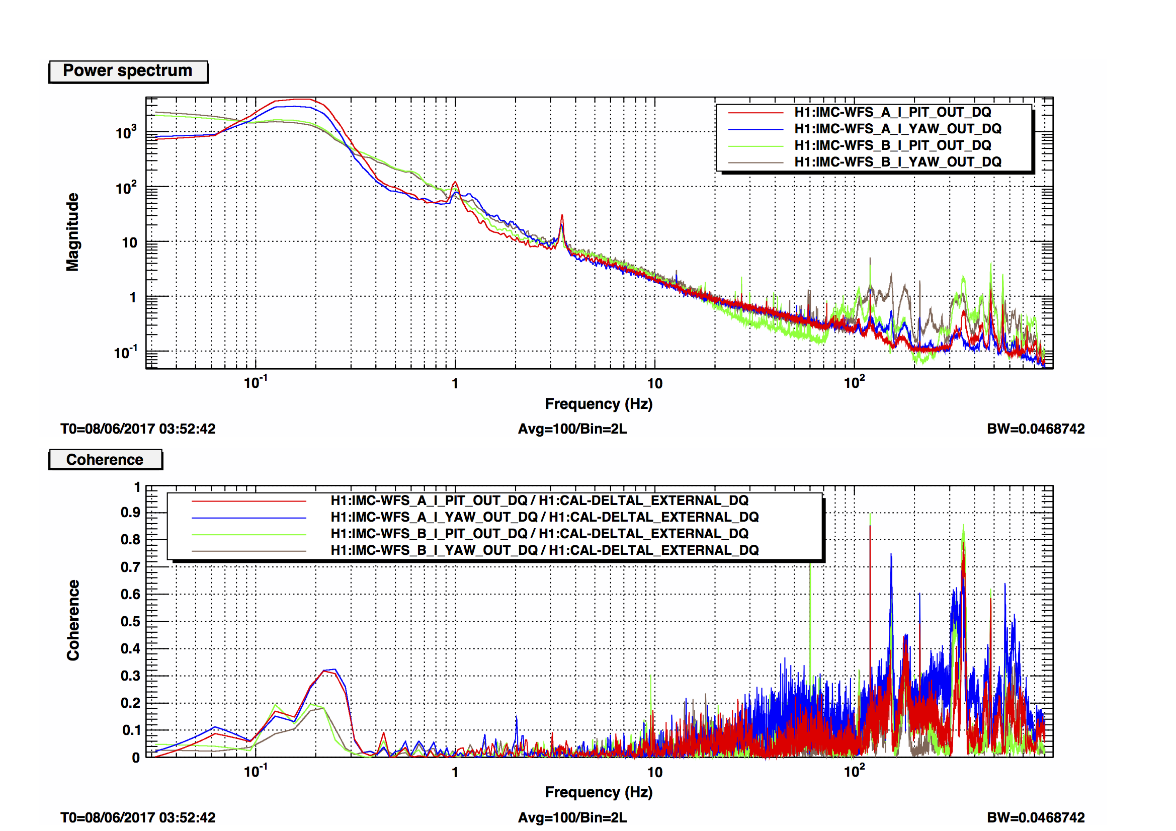
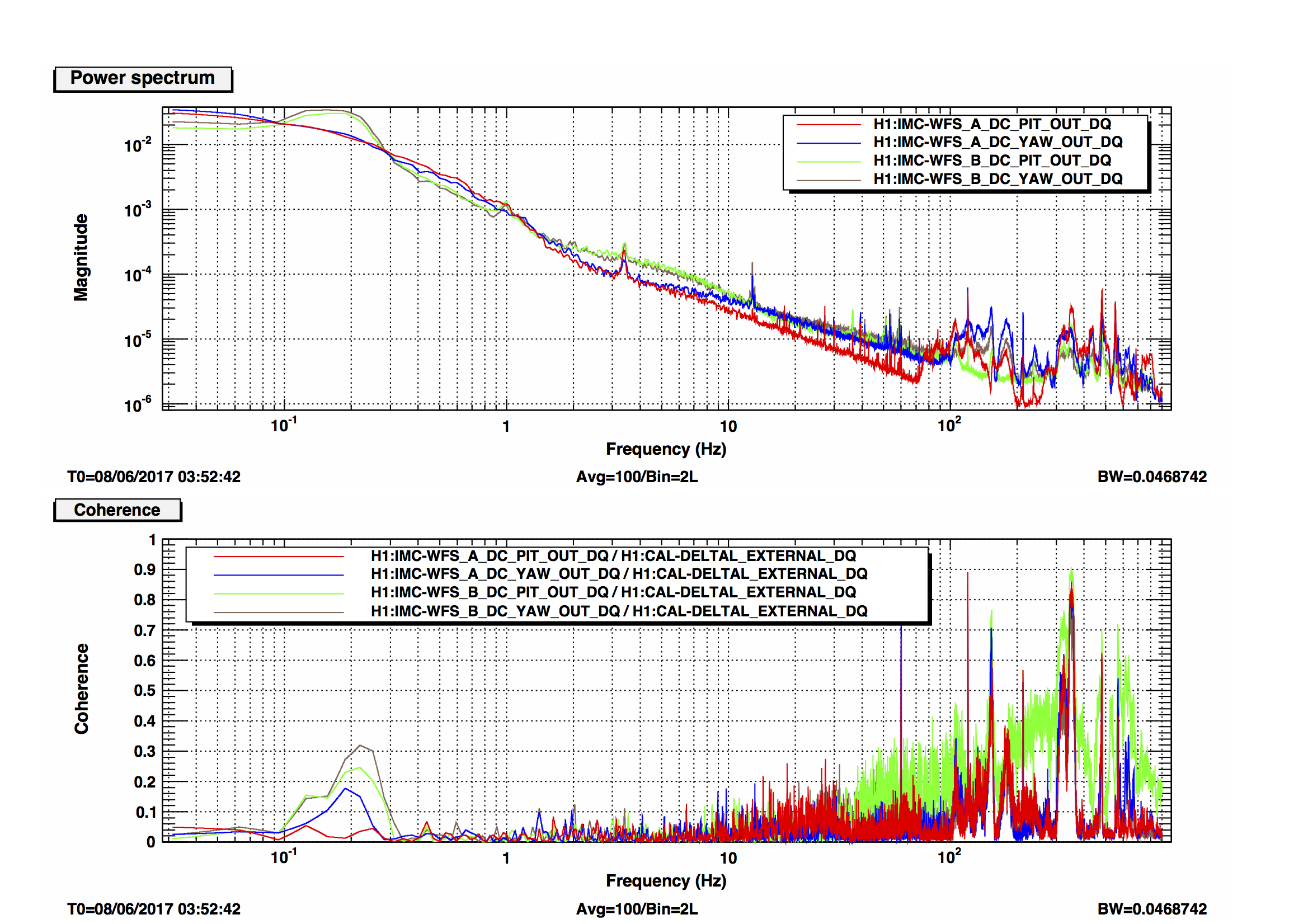
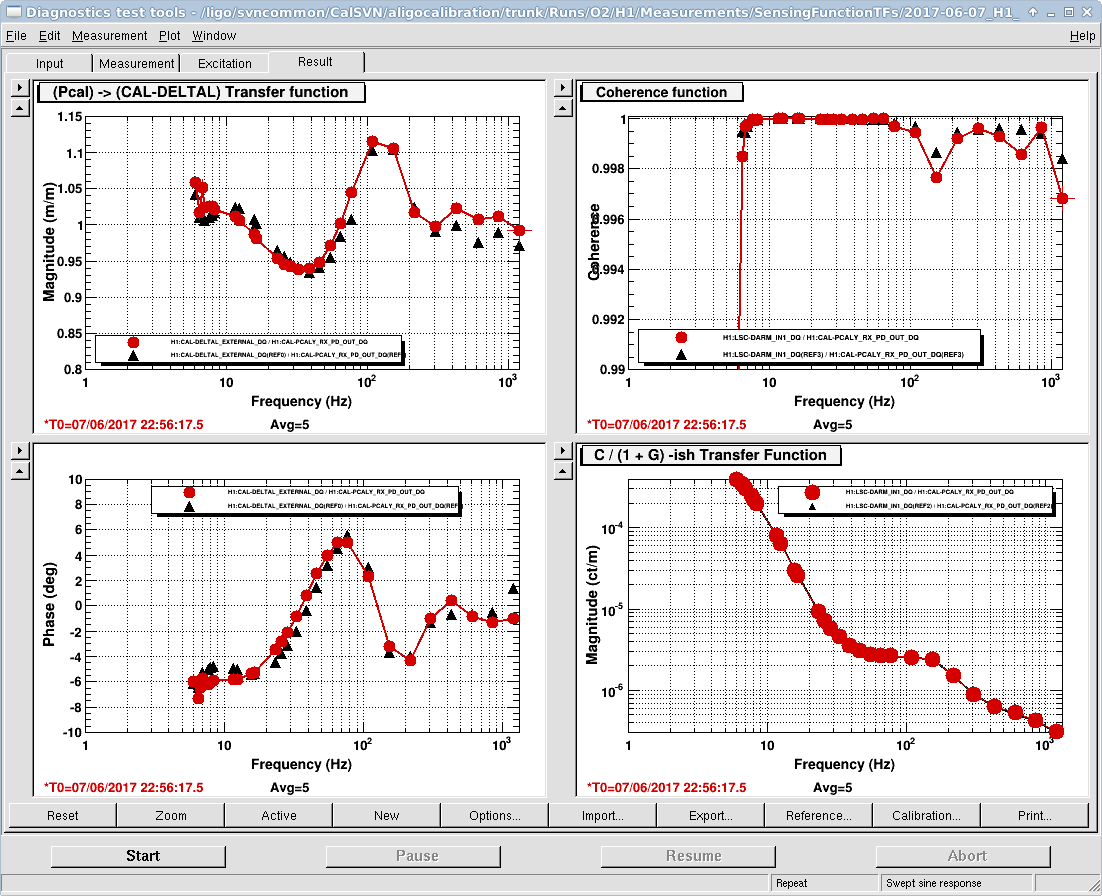
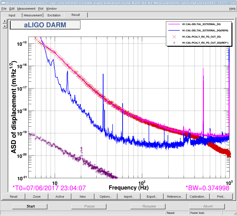
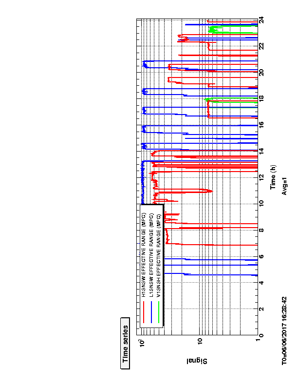
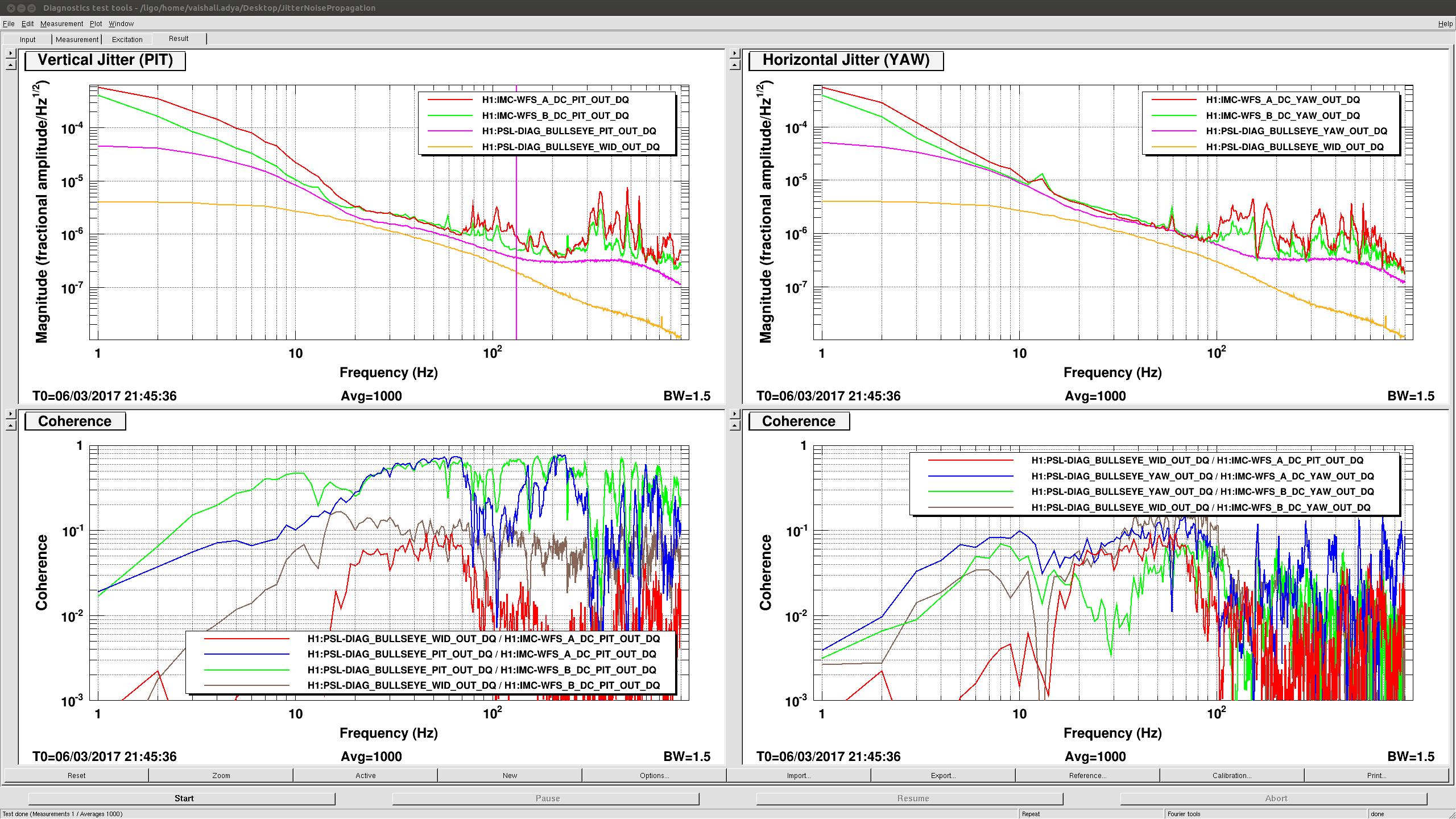
Observations/Notes : Locked in NLN at 62 MPc, Jitter noise back, super high frequency noise has gone away i.e. the DARM spectra almost looks like what it used to before the vent.
Warning : If I have forgotten something or said something wrong, Jenne will correct me in comments :)