With the higher sideband power we were limited to ~2 kHz ugf in the PMC with the lowest gain settings. Today, we changed resistor R19 to 4.75K from 1.21K which reduced the electronics gain by about 2.
While having the servo board in the shop we check R16/R17 which are 9.09K/1.00K rather than the 19.6K/1.00K indicated in the schematics. This explains the gain mystery described in alog 31120. The calibration of the slider has been changed is now accurately going from 0dB to 40dB.
We measured the transfer function with 0 dB, 12 dB and 22 dB of gain. The servo goes unstable at 25 dB, so 22 dB should be the maximum used. The ugf was around 1.1 kHz, 3.2 kHz and 9.4 kHz, respectively.
The reason we are not able to go below 1 kHz ugf is todays PSL change which improved the mode matching into the PMC and increased the optical gain (maybe by a factor of 2).
Our new Inficon Bayard Alpert vacuum gauges have a drift issue. The plot shows three gauges in the corner; PT170, PT180 vs PT120 (cold cathode). The cold cathode is trending flat or down while the two inficons are trending up.
The two inficons located in the two end station are flat, however.
Perhaps the upward drift on the two LVEA gauges is due to some "wet" hardware the gauge was mounted with??Gerardo plans to talk with technical folks at Inficon. The LVEA gauges are mounted on BSC 7, BSC8 and BSC2(PT120 cold cathode)
WP6287 Add PEM ADC to h1oaf0, reconfigure h1iopoaf0 to read new ADC
Jim installed a 7th ADC into the h1oaf0 IO Chassis this morning. On power up, the IOP model did not start well and reported ADC and DAC errors.
Since we were to restart the h1iopoaf0 model to clear the DAC errors, we installed the new code which reads the new ADC.
After running for about an hour, the h1oaf0 machine stopped making new network connections with the console error
nf_conntrack: table full, dropping packet
repeating frequently. On h1lsc0 we issued the command to remotely take h1oaf0 out of the corner station dolphin fabric, and on h10af0's console we issued the command for it to prepare-shutdown from the fabric. With no connection between h1oaf0 and h1boot (dolphin master) we had little confidence we could reboot h1oaf0 without glitching most of the corner staiton.
Researching the error, we found that it is possible to expand the netfilter connection tracking table size on-the fly with the command
echo 256000 > /proc/sys/net/netfilter/nf_conntrack_max
(the max is at the default of 65536).
This cleared the error and new MEDM's and Guardian could establish CA links, and we could SSH onto the machine. At this point we again issued the dolphin prepare shutdown command with more confidence that it was successful, but there is still a chance of corner station crash.
We will make the larger table size the default by creating the file on the boot server (h1boot)
/diskless/root/etc/sysctl.conf
with one line
net.netfilter.nf_conntrack_max = 256000
will test this on the reboot of h1oaf0 (waiting for a good time if a CS crash is precipitated)
Note that around the time of the nf_conntrack errors the IOP reported ADC and DAC errors. It is still a possibility that the new ADC was the cause of these errors and may be removed it another error is seen.
Will likely propagate to LLO when possible
looks like our change to /etc/sysctl.conf didn't work and the front end computer had defaulted back to 65536. We manually set it to 256000 for now.
The online h(t) pipeline has been restarted at LHO, following a software upgrade to gstlal-calibration (see https://versions.ligo.org/cgit/gstlal/tag/?h=gstlal-calibration-1.0.7-v1 and Redmine issue https://bugs.ligo.org/redmine/issues/4813#change-20027). We are applying a coherence uncertainty threshold of 0.004 for the online calculation of kappas, which is consistent with behavior observed during recent lock stretches (see the figure attached).
This update adds six new channels containing kappa values not gated by the calib_state_vector or by coherence uncertainties:
Note, the filters have not been updated for this pipeline restart. We are still using the filters documented in this aLOG: https://alog.ligo-wa.caltech.edu/aLOG/index.php?callRep=30210.
[IFO]:GDS-CALIB_KAPPA_A_REAL [IFO]:GDS-CALIB_KAPPA_A_IMAGINARY
[IFO]:GDS-CALIB_KAPPA_A_REAL [IFO]:GDS-CALIB_KAPPA_A_IMAGINARY
Note that aggregation of hoft by DCS into 4096 s H1_HOFT_C00 frame files will pick up this change starting from 1162672336 == Nov 08 2016 20:31:59 UTC.
The work in alog 31308 (which involved an h1oaf restart) took the TCS chillers down, which subsequently took the lasers down. Richard/Gerardo restarted the chillers and the lasers (~9:30am PT). After a bad restart of h1oaf which caused some confusion, the 2nd or 3rd restart was finally successful and the FE servos took over to adjust the laser temps/powers to nominal. Here's the notes we gathered from today which we will write in an ops wiki:
If h1oaf gets booted and the chillers go down, you only need to restart the chillers at the front panel and the lasers at the racks on the floor. The TCS settings come back up properly with the safe.snap. If the front end is not up yet, the SDF may show some stale setting diffs. Ignore anything in SDF until the FE is back up - most of these diffs will take care of themself as many are servos that do automatic adjustments.
Doh - 10:52am PT - h1oaf "just died" - CDS working on it...
As of 10:40PT, 18:40UTC
Work going on
Still to come:
I have rebuilt daqd fw on h1fw2 using a new ldas-tools build (2.5.2). This is the version in use at LLO and contains updated leap second tables. The plan is to compare the output from h1fw2 to h1fw0 and h1fw1 for a week and then migrate h1fw0 and h1fw1 to use the newer framecpp releases next week. In the mean time the daq status page will show differences in the frames between h1fw2 and the other frame writers. This is due to framecpp encoding a different version string in the frame file. Dave will update the daq overview screen to help minimize the differences. This is under workpermit 6303.
As Dave was reworking the DAQ overview screen we noticed an artifact of the daqd fw code. The framecpp version information is only written to full frames (science/commissioning) not to trend frames. So the switch to a newer FrameCPP version introduces a difference in checksum and file length in the science frame as the version string has changed. However there is no change to the minute or second trend files. It would probably be good to have the version string injected into the minute/second trend as well to help figure out issues (if they arise)...
Trended LVEA pressure gauge readings over 60 days. We have seen a trend upward in the two new hot cathode ion gauges PT 170 & PT 180 on BSC 7 & 8. Last Tuesday we degassed both to see if that helps stabilize the readings (cold cathode gauges, PT 120B, 114B, 134B, readings in corner are either flat or trend down!). PT 140 is the one and only gauge measuring diagonal volume, and is also a new hot cathode ion gauge. It was reading pretty flat, until Oct. 10th when the temperature in LVEA was increased at 2B area (west corner) by around 1/2 degF. PT110 is a new hot cathode gauge on HAM 6.
WP 6287 Installed additional ADC in h1oaf0 I/O chassis, bus slot 2-8. 8:05 PST powered down h1oaf0 computer, I/O chassis. Installed new ADC and interface card. Powered down TCS AI chassis, powered up I/O chassis. Remotely started h1oaf0 computer, verified card was detected, powered TCS AI chassis back on. Out of CER at 8:25.
I have switched chillers at the corner station from Chiller 1 to Chiller 2. This is simply to try and distribute the run time somewhat evenly between the three chillers. Temperatures should remain the same.
Nutsinee, Stefan
As suggested by alog 31304, we set up a 26:74 mixed input matrix element for PRCL in the next lock:
POP_A_RF9_I to PRCL = 0.0091
REFL_A_RF45_I to PRCL = -849 (yes, a minus sign)
This gave us the expected additionbal slight improvement in PRCL sensing, see the attached plot.
Indeed, this auxiliary noise reduction seems to have given us a range increase of about 5% to 75Mpc.
More importantly though, suddenly the range seemed to be rock-sold, without any up- and down drifts - see the last hour in the attached range plot.
Still to do: PRCL FF & possible modulation depth increase.
After this first step the return will not be as big in terms of range, but the improvement in range stability by itself makes it worth the effort.
We put all this into Guardian (NOISE_TUNINGS), but we didn't test the Guardian yet (the interferometer was too steady).
This is a follow up comparing the ADC noise, the dark noise and measured spectra. ADC noise is about 0.005 cts/√Hz at the input of the filter module. The following table gives the ratio of dark to ADC noise and the ratio of measured noise to dark noise above ~20 Hz.
Photodiode Channel |
Whitening Stages |
Ratio dark/ADC |
Ratio |
---|---|---|---|
REFL_A_RF9 | 2 | ~10 | ~4/3 |
REFL_A_RF45 | 1 | ~4 | >3 |
POP_A_RF9 | 1 | ~2 | >3 |
POP_A_RF45 | 1 | ~30 | >2 |
The strange gain ratio for the POP9/REFL45 combination is partially explained by a cts2V filter bank that is enabled in REFL45.
We did a final CO2 exploration at an input laser power of 25 W today. This was to fine-tune the CO2 settings that the operators have explored in the past weeks (31048, 30974).
In the end I set the CO2X power back to 0.3 W (which was recently set 31246) which gave us the highest BNS range. Not sure if the addition of the IMC WFS offset (31246) changes the story here.
[The test]
The TCS test started at around 19:14 UTC today. The interferometer has been locked for more than 10 hours at that point with an input laser power of 25 W. The CO2 settings before the test was [CO2X, CO2Y] = [300 mW, 0 W]. This is something Sheila set during the weekend (31246). Here is an imcomplete list of time lines.
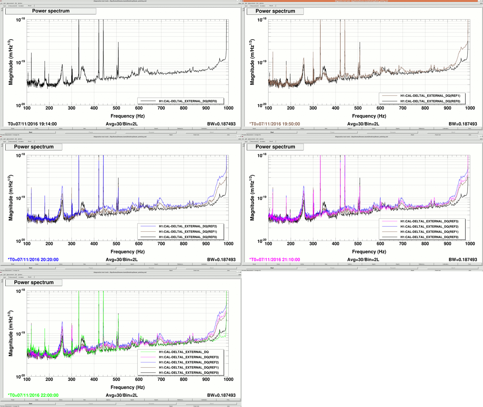
In the above list, the letters in the square brackets correspond to the labels in the dtt spectra shown below. A trend of this test are shown in the first attachment. LOCKINs 1 and 2 were monitoring the coupling transfer coefficients from the PSL periscope PZT to DARM for pitch and yaw, respectively. The pitch excitation was at 441.3 Hz and the yaw was at 421.1 Hz.
[The results]
The DARM spectra from different times are shown below.
As the CO2X increased, noise around 350 Hz and 620 Hz decreased. This behavior is qualitatively consistent with what I have seen in the LOCKIN demodulators, especially the yaw coupling or LOCKIN2. However, obviously, this improvement came with higher noise elsewhere. In particular, the 260 Hz peak became quite noticeably worse by a factor of 3 at most. Also, the side lobe of the 1 kHz violin modes became significantly worse too by a factor of roughly 2. This time, I did not check laser noise couplings (intensity or frequency) simultaneously. According to the sensmon shown in the first attachment, increasing CO2X decreased the BNS range by 5 Mpc or so. The DARM spectrum below 100 Hz seems to have stayed the same throughout the test.
J. Kissel I've taken the first round of all swept sine measurements typically done before an observing run: (1) Sensing function, C (a) DARMOLGTF and Loop Suppression (IN1/IN2 and IN2/EXC); G and 1/(1+G) (b) PCAL2DARM (and PCAL2DELTAL); (C/1+G) and [m/m] (2) Actuation Function, A (a) L1 to DARM & associated PCAL2DARM; (C A_uim)/(1+G) and (C/1+G) (b) L2 to DARM & associated PCAL2DARM; (C A_pum)/(1+G) and (C/1+G) (c) L3 to DARM & associated PCAL2DARM; (C A_tst)/(1+G) and (C/1+G) where I've taken a separate PCAL2DARM or C/1+G transfer function with every corresponding excitation to destroy any covariance that had plagued us during O1. Also, I've worked to (i) reduce the template's measurement time by maximizing drive, (ii) reducing the number of points over all, and (iii) keeping integration time in check, such that each template only takes about 15 minutes. I've also modified the frequency vectors of the actuation functions to go out to 1 kHz, as LLO did for their O1 data sets. In doing so, I made sure to use frequency points that avoided any known high-frequency resonances from wire violin modes (characterized in LHO aLOG 24917). There's still some improvements to make, which I'll shoot for in the next round (so don't use/take these templates as cannon yet), but thanks to the high-duty cycle of the IFO, I had the opportunity to make really well-balanced templates tonight. The data lives here: /ligo/svncommon/CalSVN/aligocalibration/trunk/Runs/ER10/H1/Measurements/ (1a) DARMOLGTFs/2016-11-07_H1_DARM_OLGTF_4to1200Hz_fasttemplate.xml (1b) PCAL/2016-11-07_H1_PCAL2DARMTF_4to1200Hz_fasttemplate.xml (2) FullIFOActuatorTFs/2016-11-07/2016-11-07_H1SUSETMY_L1_iEXC2DARM.xml FullIFOActuatorTFs/2016-11-07/2016-11-07_H1SUSETMY_L1_PCAL2DARM.xml FullIFOActuatorTFs/2016-11-07/2016-11-07_H1SUSETMY_L2_iEXC2DARM.xml FullIFOActuatorTFs/2016-11-07/2016-11-07_H1SUSETMY_L2_PCAL2DARM.xml FullIFOActuatorTFs/2016-11-07/2016-11-07_H1SUSETMY_L3_iEXC2DARM.xml FullIFOActuatorTFs/2016-11-07/2016-11-07_H1SUSETMY_L3_PCAL2DARM.xml While it'll be days before we have a model and a complete, traceable uncertainty budget, preliminary results show the *mean* of *one measurement* of PCAL's estimated displacement agrees with the front-end calibrated sensitivity to roughly 5% and 5 [deg]. This confirms that the > 50 Hz discrepancies between PCAL and DELTA L EXTERNAL seen while we were at 50 [W] (e.g. LHO aLOGs 30391 and 30431) were likely a function of the poorly controlled signal recycling cavity, and therefore time-dependent RSE cavity pole that was quite low. Recall that the uncertainty of the PCAL estimation is around 1%. We're right on schedule, and things are looking up. We'll see how the modeling goes...
DARM actuation spectra are attached.
We could do a bit better in offloading the microseism control from the PUM to the UIM.
SRC1 loops (P&Y) are ON Input Power Mean: 23.5 [W]
I succeeded in switching PRCL over to REFL_A_RF45_I.
This improved the sensing noise between 30Hz and 100Hz by about a factor of 2.
We did this in the middle of an earthquake, and eventually lost lock, so I didn't put it in Guardian yet. We also had more than usual scattering due to the earthquake, so it is too early to tell whether it made a DARM noise difference.
Also:
- We should investigate increassing (or better: not reducing) the RF45 modulation index.
- By mixing POP_A_RF9_I and REFL_A_RF45_I to PRCL by about 0.26:0.74 we should get another ~25% shot noise reduction.
- The first lock looked promising, but if for some reason we still have a DC drift problem on REFL, we could blend it to POP_A_RF9_I at DC
Matrix elements:
replaced the old
POP_A_RF9_I to PRCL = 0.035
with the new
REFL_A_RF45_I to PRCL = -1147.5 (yes, a minus sign)
The PMC length noise no longer shows up in DARM. Even for the 1 kHz and 4 kHz peaks there is a factor of a few safety margin. Increasing the PMC gain slider from 0 dB to 16 dB (actually from 0 dB to 12 dB), we see no significant change in DARM. The 4 kHz peak starts touching the noise floor with a 0.3 coherence.
This means that the increased coherence between DARM and jittery peaks after the increase in the modulation depth and associated PMC changes (alogs 31095 and 31203) is a mystery.
We are running about 8dB higher PMC length gain than before as that's the lowest we can go with the current electronics with higher modulation depth. It would be interesting to see if modifying the electronics will do anything.
(In the attached, IMC_F and IMC-WFS traces are scaled arbitrarily such that it's easier to make an eyball comparison.)
J. Kissel, D. Tuyenbayev We're still not getting the IFO duty cycle to get the desired uncertainty on the single-frequency actuation strength scale factor measurement of the UIM and PUM stage and we're running out of time, so I've increased the SNR of these temporary lines by another factor of ~3 over yesterday's increase (see LHO aLOG 31108). Oscillator Freq (Hz) Old Amp (ct) New Amp (ct) ETMY UIM 33.7 180 500 ETMY PUM 34.7 81 300 Hopefully Robert's activities tonight won't impact the ~30 Hz region of the sensitivity, and we can turn things off soon.
Jeff K, Darkahn T,
We calculated actuation strengths of L1 (UIM), L2 (PUM) and L3 (TST) actuation stages using calibration lines from 6 lock stretches in the last two days.
Preliminary results are given in the attached plots. Standard deviation on estimations of AU and AP are ~1.2% and for AT is ~0.4%.
Data points were taken at GPS times with HOFT_OK_BIT = 1 (segments are listed below).
# seg start stop duration
0 1162123790.0 1162124750.0 960.000
1 1162124840.0 1162125190.0 350.000
2 1162125280.0 1162125480.0 200.000
3 1162127120.0 1162129210.0 2090.000
4 1162134280.0 1162137150.0 2870.000
5 1162162170.0 1162163370.0 1200.000
Increased line amplitudes will hopefully allow us to get AU and AP actuation strengths with subpercent 1-sigma error bounds.
Jeff K, Greg M, Darkhan T,
After the L1 and L2 line amplitude increase it seems that we got better uncertainties in the esitamtions of the sus. stage actuation strengths.
This time we filtered the data using the IFO range channel, we used 50 MPC as a threshold. And from the remaining data we made historams of three different time intervals. We did not yet investiage why the noise levels of the lines are different at each of these intervals. The uncertainties for A{U,P,T} are given for the least noisy interval (blue data points).
Jeff K, Greg M, Darkhan T,
We calculated [N/ct] actuation force factors calculated from the ~35 Hz independent L1, L2 and L3 lines:
KU = 8.012-8 +/- 3.873-10 N/ct ( std(KU) / |KU| = 0.0048 )
KP = 6.482-10 +/- 2.748-12 N/ct ( std(KP) / |KP| = 0.0042 )
KT = 4.253-12 +/- 1.679-14 N/ct ( std(KT) / |KT| = 0.0039 )
During a Nov. 4 lock stretch we got a factor of 3 improvement of the standard deviations compared to the previous day (blue data points vs. green).
In most recent 2 days we got more data with longer lock stretches, which can help us to better bound the uncertainties. Analysis of this data would require including an updated DARM digital filters, the IFO response changed on Nov. 5 (see LHO alog 31201) which can bias on our calculations if not taken into account.
The outliers were removed in a following way:
- Took >= 50 MPC data and removed data points that fall outside of 2-sigma std. deviation (some large outliers were not filtered by this step);
- one more time calculated std. and mean in the remaining data points and removed 2-sigma outliers (this step helped to remove large outliers).
- The mean and 2std. of these data points were shown with black solid line and dashed lines.
The final reported mean values and standard deviations were taken from the blue data points ( GPS [1162252470, 1162271230] ), L1 and L2 data was least noisy during this period. This mean value and its std. were shown with blue solid and dashed lines.
Started yesterday evening. Doesn't seems to be equally spaced.
It could be pickup through the unshielded part of the RTD cable (where it comes out of the laser), but it's strange that it started in X and Y at the same time. Can you check the FLIR cameras are turned off on the MEDM screen.
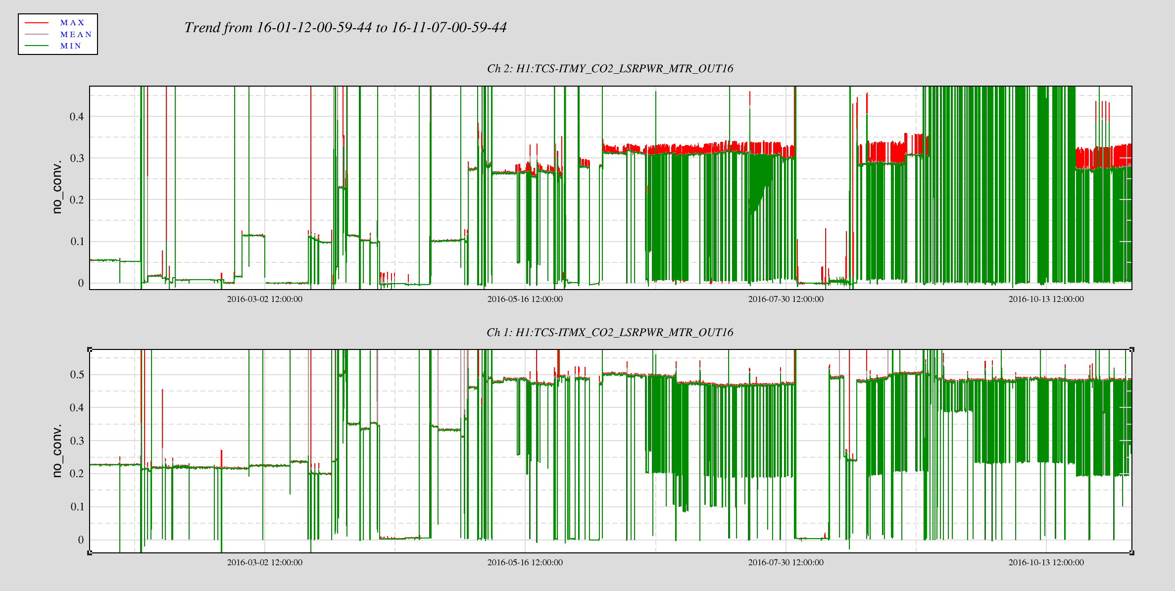
Apparently there is a "glitch" in the laser power of both X and Y TCS systems every time the Laser power meter sees a request for a power change. (see 1 day trend with additional channels to correlate with). However, this did not just start yesterday, it has been going for at least a month (see second plot of the last 3 days). I spot checked back a month and the behavior is the same. Note, there are a few extra spikes on these channels but this doesn't seem to be new behavior.
Update: I looked closer at these glitches.
Characteristic:
A single glitch spans across multiple sample points, lasted a little less than half a second. Almost everyone of these glitches lead by one smaller glitch that's roughly 1.5 second apart, followed by an even smaller glitch and immediately followed by a larger glitch.
Timeline:
I looked back several months and it seems like these glitches started to show up much more frequently on May 13th this year (started at 16:28 UTC to be precise). I looked back on the alog and didn't find any invasive work with the TCS on May12th or 13th.
OLTF pictures.
For the first plot we compare the ILS and PMC error and control spectra before and after today's change.The ILS gain is unchanged, whereas the PMC gain slider was set to 6 dB to make the ugf similar to before. We did not apply the 770 Hz pole that is formed by the PZT and the output resistor. The following observations can be made:
For the second plot we set the PMC gain to 0 dB:
The power on the locking diode has been held constant—even so the mode matching improved by ~2. This indicates that the peaks scale with the total power on the locking PD and are not related to frequency or length noise.