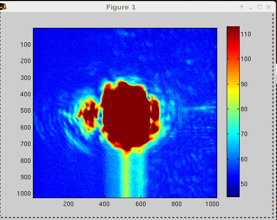
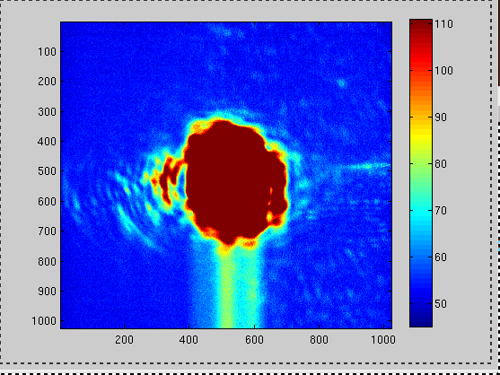
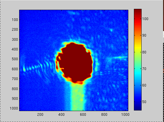
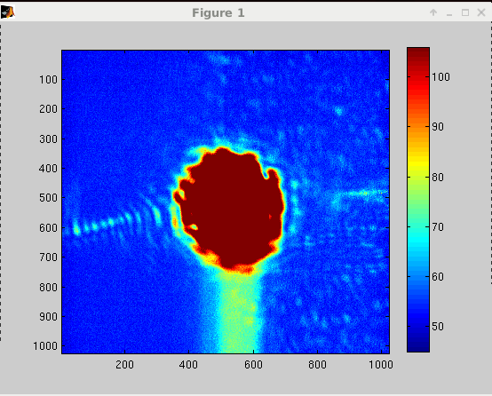
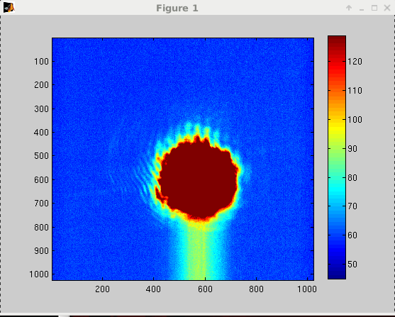
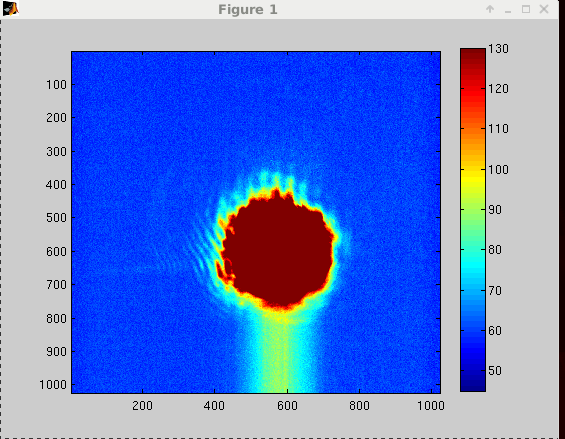
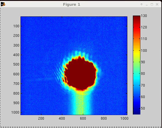
To be able to take measurement with HWS at the end stations we need a proper PZT offset for both EX and EY to get rid of the reflection coming off of the ITMs during full lock (when the arm is locked in RED). Today I tested Elli's EX PZT2 offset from 2 years ago (alog17860) while taken the past and current PZT2 YAW output into account. A quick conclusion is the sum of output + misalign bias that Elli figured out still gives goodish image on the HWSX camera, but needed fine tuning.
How to lock arms in red (one at a time, this is for X arm)
1) Request INITIAL_ALIGNMENT on the ISC_LOCK guardian, take ALIGN_IFO to DOWN then request XARM_IR_LOCKED
2) If ALIGN_IFO guardian stuck at LOCKING_XARM_IR, the arm is too misalign. Do INITIAL_ALIGNMENT for the arm that you want (or both)
Once the arms are locked in green, they are good for red too. Go back to LOCKING_XARM_IR
Guardian will misalign PRM, SRM, ITMY, and ETMY. Make sure no one else is using these.
Misaligning ALSX PZT2
1) Turn off H1:ALSX_PZT2_YAW_OUTEN. This is an ON/OFF switch. The switch can be found in SITEMAP>ALSX Overview, PZT2_YAW
Make sure you stream image so you can see the transition
2) Add YAW offset to H1:ALS-X_PZT2_YAW_MISALIGN_BIAS
3) Type of misalignment => make it SUM
4) Click Misalign.
To revert the configuration, make sure to watch out for the growing output before turning the OUTEN switch back on. If the number grows, turn the integrator off and bleed rate on. The counts will slowly ramp down.
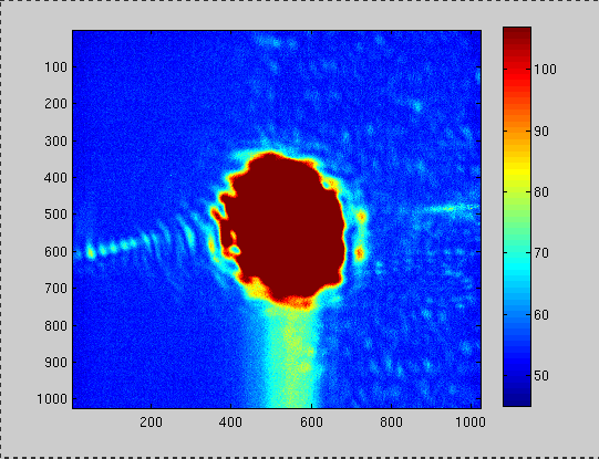
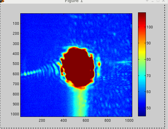
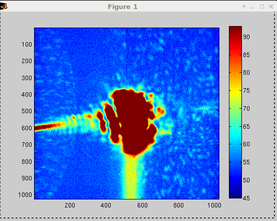
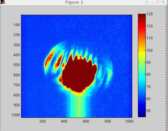
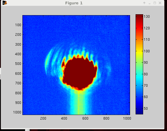
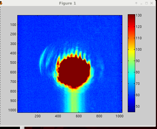
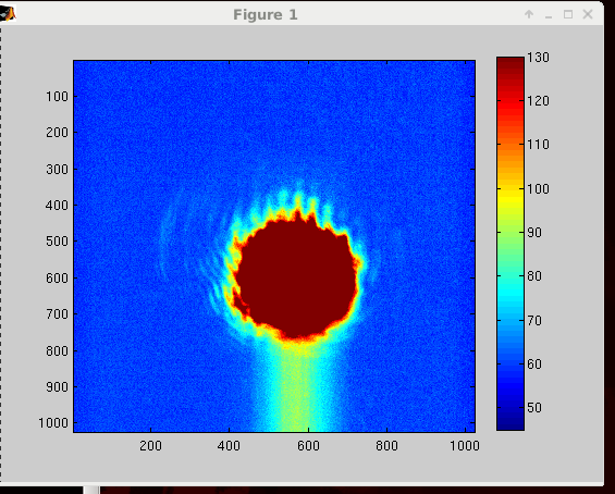
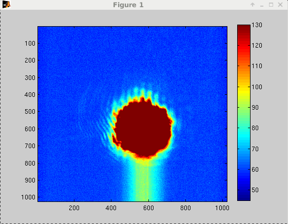
I compared my streamed images to Elli's using the same matlab script. But the images don't look quite the same (mine seem a bit more saturated). On April 24 I calculated the more recent offset to be -3381. This result in a very clipped-looking image on the HWSX so I went backward a little. -2400 seems to have given the best result. Today's PZT2 YAW output (~10340) + misalignment bias (-2400) sum up to be 7940, 321 counts different from Elli's sum (10919-3300 = 7619).
I'm afraid that ITMs alignment might also affect this offset. If there's no more commissioning time this week to take the data the offset should be checked again after the vent.
We had no problem going back to NLN later. If there was any hysteresis, it didn't case a problem.
HWS plates are currently off at both end stations.


Jitter coupling is back to pre-O2 level, attached is the coherence between DARM and IMC WFS DC from last evening. Even at 60Hz the coherence is still about ~0.1.