3:41: Lockloss
PSL Issues: (I marked some CORRECTIVE MAINTENANCE time, but not sure this is FRS-worthy):
Corresponding with this lockloss, had the following PSL Guardian Messages:
- ISS Diffracted Power Low
- Noise Eater: NPRO Out Of Range
For ISS Diff Power (it was oscillating between 3-14), I turned OFF the Autolocker, clicked Manual & I thought I turned it OFF---so I could tweak the Ref Signal, but I didn't have luck here. I tried restoring everything.
Since Noise Eater was RED/Off, I went out to the LVEA to toggle the switch. This made the Guardian Messages go away, and I went about locking.
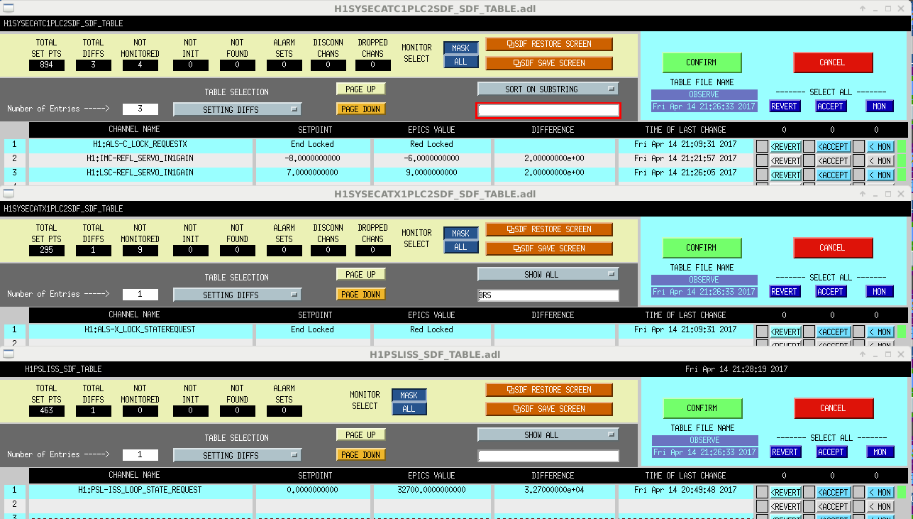
SDF Diffs & Servo Gain Changes
Upon reaching NLN, had a few diffs (attached).
- ALS ethercat state requests: Once again, ALSx was found requesting the "Red Locked" state. On the ALS medm, I took the request (H1:ALS-X_LOCK_STATEREQUEST) to "End Locked" state. Why is this an issue the last couple of locklosses.
- ISS Loop Request was not at correct value (this was probably due to my fumbling to increase the ISS Diff Power. I believe I cleared this by clicking "Off" for the Manual window of the Autolocker.
- And then there was the IMC & LSC REFL SERVO IN1 GAINs.....
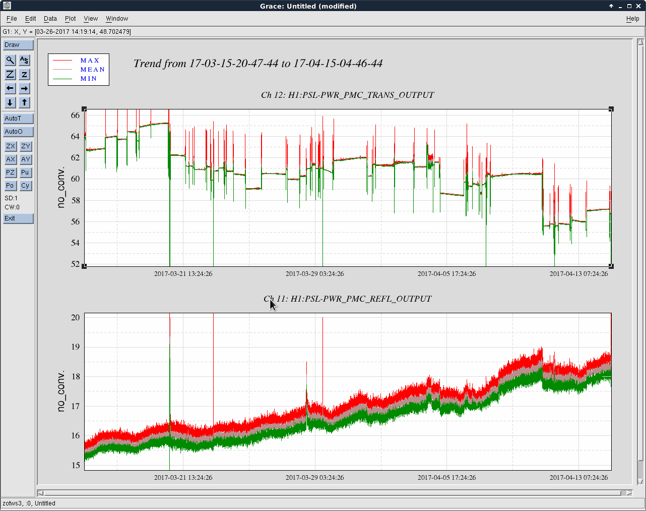
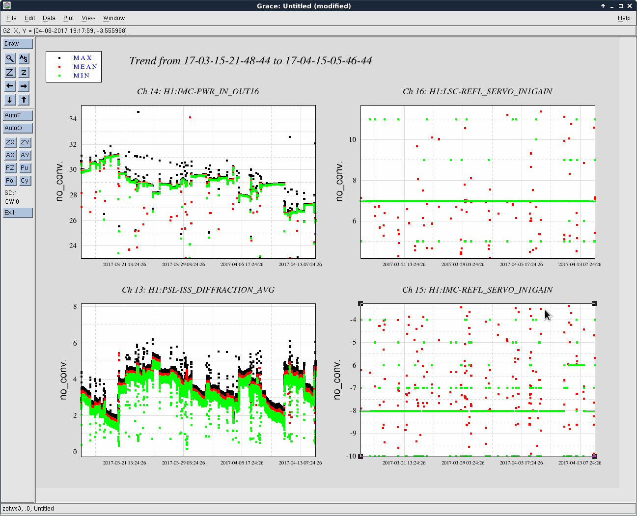
PSL Power Drifting Down, Servo Gains, & ACCEPTING Diffs Until Alignment Can Be Tweaked Up
Ended up calling Keita about these Servo Gains before attempting to go to OBSERVING.
Looks like the PSL power has been dropping over the last month (see attached IMC trends) and we finally took a jump down to where the REFL servo gains were increased & noticed by SDF (see attached trends of ISS diff power, PSL Power, & IMC/LSC REFL SERVO IN1GAINS).
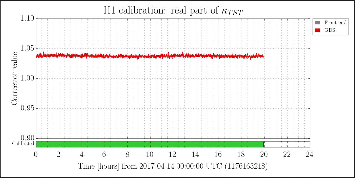
We also looked at the DARM (H1:CAL-DELTAL_EXTERNAL_DQ) spectra & compared tonight (blue) to March 19 (red). Since the high freq isn't getting increasingly noisy with higher frequency, we are OK with the SERVO gain values.
So, if we have more of these DIFFs over the weekend, we should ACCEPT them in SDF. Hopefully we can last until Peter/Jason can touch up the alignment for us next week.
5:20 Back to OBSERVING

Is this something Operators should worry about, or is it handled by others offsite? Jim & Cheryl both alogged status and that Aaron was working on/fixed it. Just wondering if this rises to the state of needing an alarm because it affects H1 data, or does it just mean one of our tools is having an issue (i.e. GWI.stat being yellow and the Daily Summary Pages reporting an on BNS range).
Should we be checking the GWI.stat through the shift (I can put it in our Shift Check Sheet), or is this something we leave to off-site staff? For GWI.stat's Help Page it says we should report bugs to Peter Shawhan. I'm not sure of who we report Summary Page bugs to.