jeffrey.bartlett@LIGO.ORG - posted 16:03, Wednesday 12 April 2017 (35508)
Ops Day Shift Summary
Ops Shift Log: 04/12/2017, Day Shift 15:00 – 23:00 (08:00 - 16:00) Time - UTC (PT)
State of H1: Locked at NLN
Intent Bit: Observing
Support: Sheila, Dave, TJ,
Incoming Operator: Travis
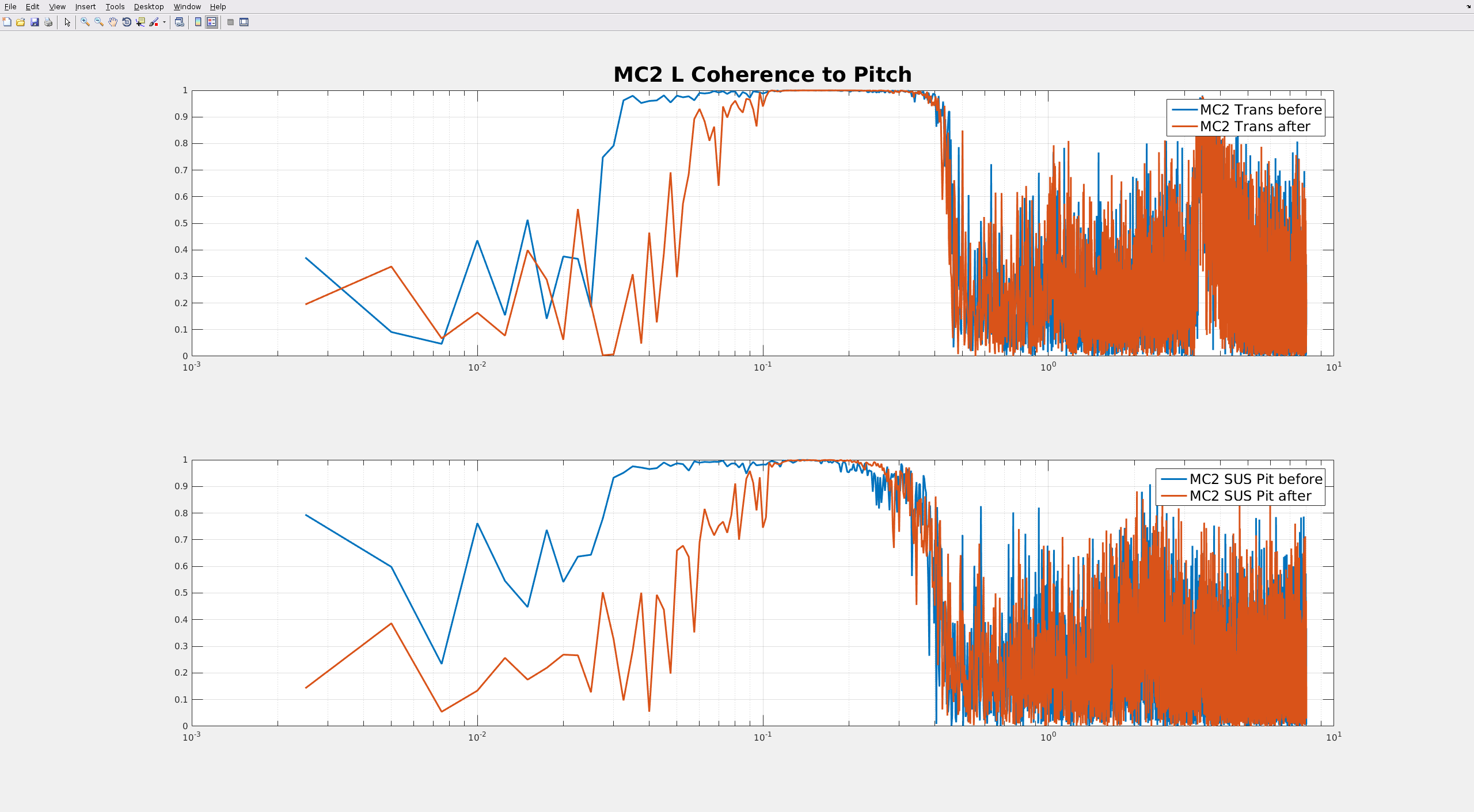
Shift Summary: Drop out of Observing for start of commissioning window. Run A2L check script. Yaw is up to 0.8, Pitch is a bit above 0.4. Run the A2L repair script. Relocked after commissioning Lockloss.
Per Keita – The commissioning window has been extended until 21:00 (14:00).
Relocked after commissioning Lockloss. Back to Observing.
Activity Log: Time - UTC (PT)
15:00 (08:00) Take over from Nutsinee
15:20 (08:20) Kingsoft on site to check RO system
15:51 (08:51) Karen – Going to Mid-Y
16:00 (09:00) Chandra – Going into the LVEA to turn off pump
16:00 (09:00) Drop out of Observing for commissioning window
16:00 (09:00) Robert – Going into the LVEA for commissioning work
16:02 (09:02) Run A2L check script
16:05 (09:05) Chandra – Out of the LVEA
16:20 (09:20) Run A2L repair script
16:52 (09:52) Karen – Back from Mid-Y
18:53 (11:53) Locke lock – Commissioning activities
18:55 (11:55) Robert – Going to End-Y to move magnetometer
18:58 (11:58) TJ – Reloading Guardian SEI Configuration Node
19:18 (12:18) Robert – Back from End-Y
19:28 (12:28) Robert – Going into the LVEA to move accelerometers
19:52 (12:52) Relocked at NLN –
20:00 (13:00) Robert – Out of the LVEA
20:08 (13:08) Damp PI Mode-28
20:32 (13:32) Lockloss – commissioning
20:45 (13:45) Robert – Going into LVEA
20:59 (13:59) Richard & Dave – Rebooting camera system
21:40 (14:40) Robert – Swept the LVEA
22:08 (15:08) Relocked at NLN and in Observing
22:26 (15:26) Damp PI Mode-28
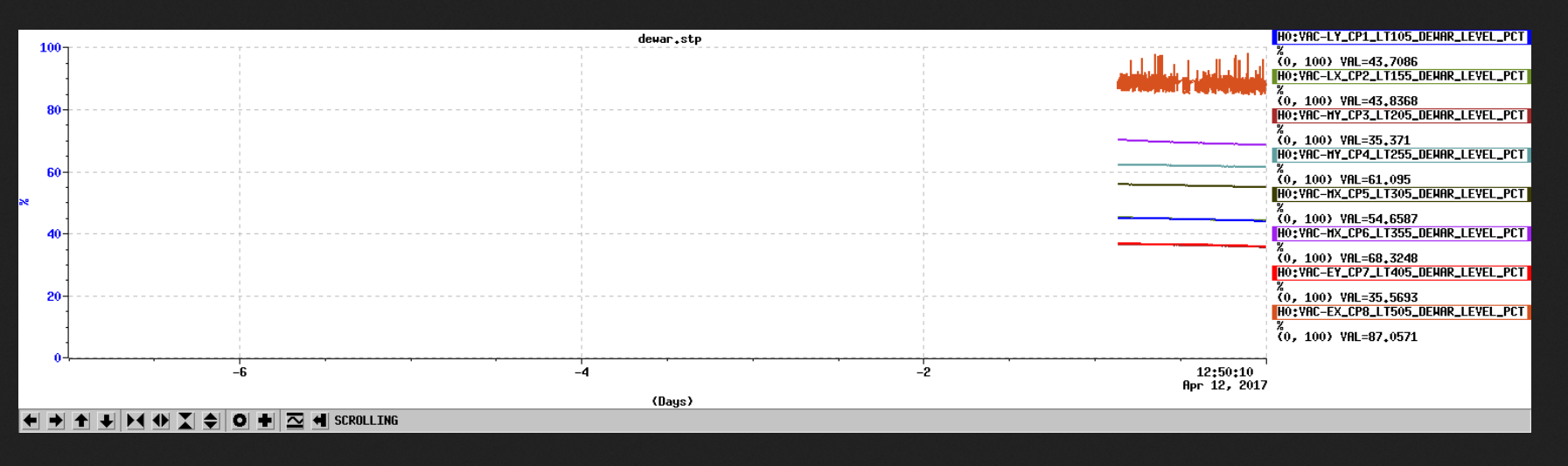
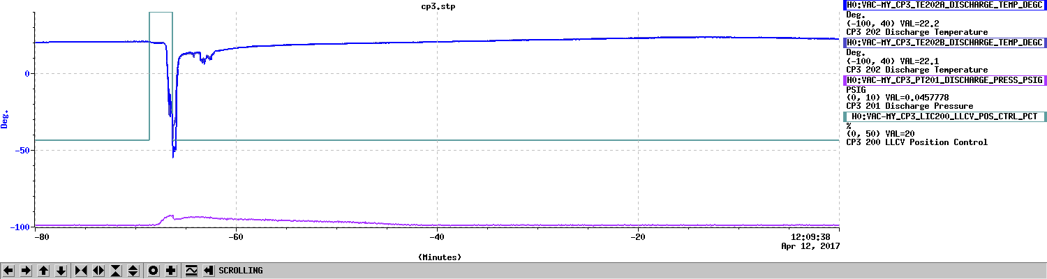
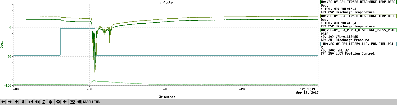
22:50 (15:50) Kyle – Going to End-X to check the N2 Dewar
23:00 (16:00) Turn over to Travis