patrick.thomas@LIGO.ORG - posted 20:01, Sunday 19 March 2017 (34930)
Ops Eve Mid Shift Summary
Have remained in observing. No changes in status or issues to report.
Have remained in observing. No changes in status or issues to report.
TITLE: 03/19 Eve Shift: 23:00-07:00 UTC (16:00-00:00 PST), all times posted in UTC
STATE of H1: Observing at 68Mpc
OUTGOING OPERATOR: Travis
CURRENT ENVIRONMENT:
    Wind: 6mph Gusts, 5mph 5min avg
    Primary useism: 0.02 μm/s
    Secondary useism: 0.18 μm/s
QUICK SUMMARY:

No issues to report.
TITLE: 03/19 Day Shift: 15:00-23:00 UTC (08:00-16:00 PST), all times posted in UTC
STATE of H1: Observing at 67Mpc
INCOMING OPERATOR: Patrick
SHIFT SUMMARY: Observing for the entire shift and 22+ hours total for this lock. Rode through a 6.0 EQ in Solomon Islands early in the shift. No issues to report.
LOG: None
6.0M Auki, Solomon Islands
Was it reported by Terramon, USGS, SEISMON? Yes, Yes, No
Magnitude (according to Terramon, USGS, SEISMON): 6.0, 6.0, NA
Location: 68km N of Auki, Solomon Islands; LAT: -8.1, LON: 160.7
Starting time of event (ie. when BLRMS started to increase on DMT on the wall): 15:40 UTC
Lock status? H1 stayed locked, L1 broke lock.
EQ reported by Terramon BEFORE it actually arrived? Not sure
Observing for 18.5 hours. No issues thus far.
TITLE: 03/19 Day Shift: 15:00-23:00 UTC (08:00-16:00 PST), all times posted in UTC
STATE of H1: Observing at 66Mpc
OUTGOING OPERATOR: Ed
CURRENT ENVIRONMENT:
Wind: 5mph Gusts, 3mph 5min avg
Primary useism: 0.01 μm/s
Secondary useism: 0.18 μm/s
QUICK SUMMARY: No issues were handed off.
TITLE: 03/19 Owl Shift: 07:00-15:00 UTC (00:00-08:00 PST), all times posted in UTC
STATE of H1: Observing at 66Mpc
INCOMING OPERATOR: Travis
SHIFT SUMMARY:
Quiet. Locked for 14hrs20min. H1 could use a2l but coincidental lock and no range loss has kept running it at bay.
LOG:
TITLE: 03/19 Owl Shift: 07:00-15:00 UTC (00:00-08:00 PST), all times posted in UTC
STATE of H1: Observing at 68Mpc
OUTGOING OPERATOR: Patrick
CURRENT ENVIRONMENT:
Wind: 15mph Gusts, 12mph 5min avg
Primary useism: 0.02 μm/s
Secondary useism: 0.20 μm/s
QUICK SUMMARY:
TITLE: 03/18 Eve Shift: 23:00-07:00 UTC (16:00-00:00 PST), all times posted in UTC
STATE of H1: Observing at 67Mpc
INCOMING OPERATOR: Ed
SHIFT SUMMARY: Winds have subsided to below 20 mph. No major issues after going back to observing. SEI is back to its nominal state (Jim W. was here after Travis lost lock due to the wind). If the winds come back up Jim W. has suggested trying the newly created 'MORE_WINDY' SEI state (see his alog).
LOG:

23:29 UTC Starting relocking.
23:51 UTC Took about four tries to get past CHECK_IR.
00:00 UTC Lock loss from SWITCH_TO_QPDS.
00:23 UTC Stopping at DC_READOUT_TRANSITION. Jim W. ramping off sensor correction.
00:25 UTC Jim W. switching SEI back to nominal.
00:39 UTC Observing.
01:02 UTC Jim W. leaving. Changed sign of gain to damp PI mode 28.
01:08 UTC Changed phase to damp PI mode 27.
06:46 UTC The bottom monitor connected to nuc6 lost its signal for ~ 20 sec.
The winds have come back down and we are back to observing.
The short version: Wind (finally, at 50 mph) gave us trouble locking today. I tried some stuff that may have helped, but I need commissioning time (and wind!) to see if it will do any good, but ALS REFL CTRL seems a good IFO witness. Everything is switched back after winds died down.
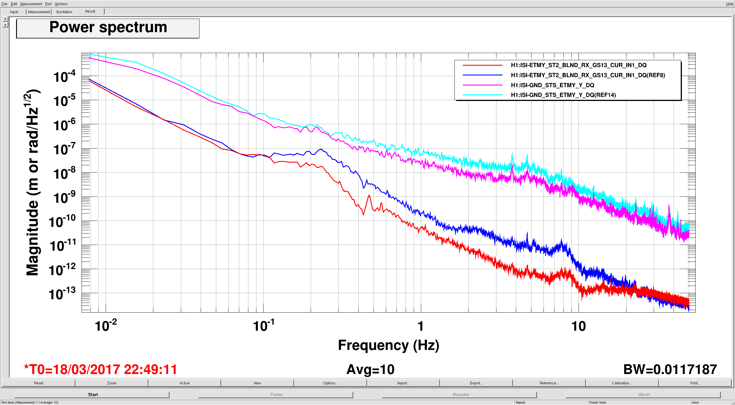
Travis started have troubles locking when we were having sustained winds around 40 mph and gusts over 50, so I came out to see if some of the stuff we've tried in the past would help. I can't really say for sure if what I've done has helped because winds have now died down, but I wanted to log some ideas. As I found in alog 30547, it would probably be beneficial to push the St1 RX/RY blends down to reduce the amount that the BSCs tilt above .1 hz, so I switched the ST1 RX/RY blends from the normal Quite_250 to the Quite_90 blends. I have also worked on commissioning St2 RX/RY loops (which we don't normally use) that improve the St2 motion at 1-10hz so I tried turning those on. We also use some sensor correction from St1 to St2 around .5hz, which doesn't hurt us when winds are below 30mph, but could couple St1 tilt to St2 motion with high winds, so I tried turning this off. The first 2 attached plots show the EY ISI St2 seismometers and the ground seismometer (which is a better indicator ground tilt than Y motion at these wind speeds).
The first plot shows the St2 RX/RY GS13s and you can see the the table is moving less between .1-20hz (blue is the "high wind" state, red is nominal), while the wind had dropped off a little (cyan to pink).
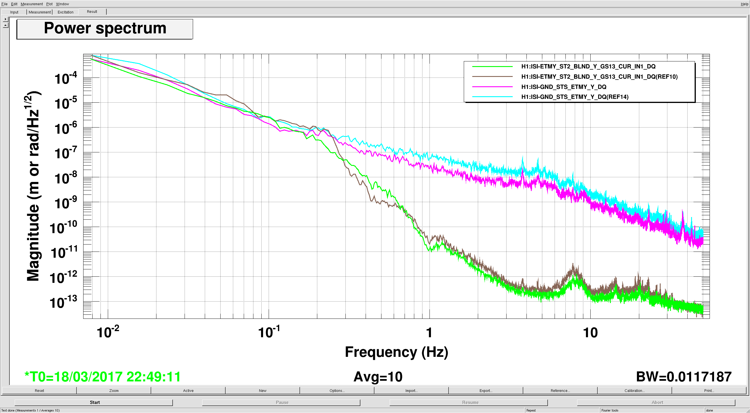
The second plot shows that this improvement in RX didn't make a drastic difference in Y (green is the "high wind" state, brown is nominal), but we gave up a bit of isolation around .5 hz by turning off the St1-St2 sensor correction.
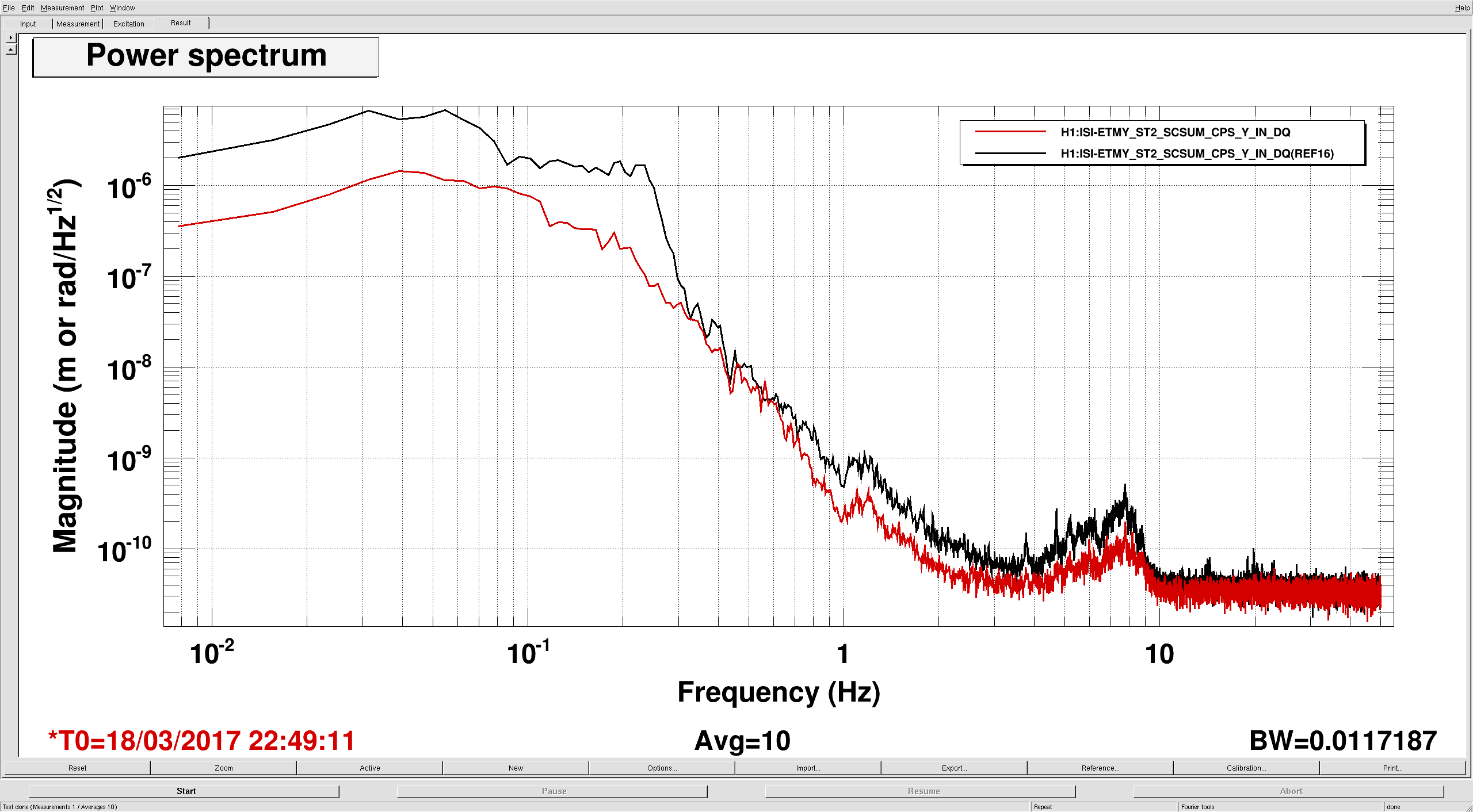
The third plot shows the difference in the ST2 CPS. Below the blend (250mhz) the CPS are a good witness of how much tilt is being injected into the table motion, so at 40 mph it would probably be a good idea to turn this off, if we can lock with more .5hz motion.
On Monday or Tuesday, I'll try to get a configuration (lower ST1 RX/RY blends, ST1-2 sc off, maybe a hack to get ST2 RX/RY iso loops on) in the SEI_CONF guardian.
I have added a state (and tested the transition while at DC READOUT) to the SEI_CONF called MORE_WINDY that turns off the ST1-2 sensor correction. Operators should try this state (MORE_WINDY) with high winds (40+) and low microseism.
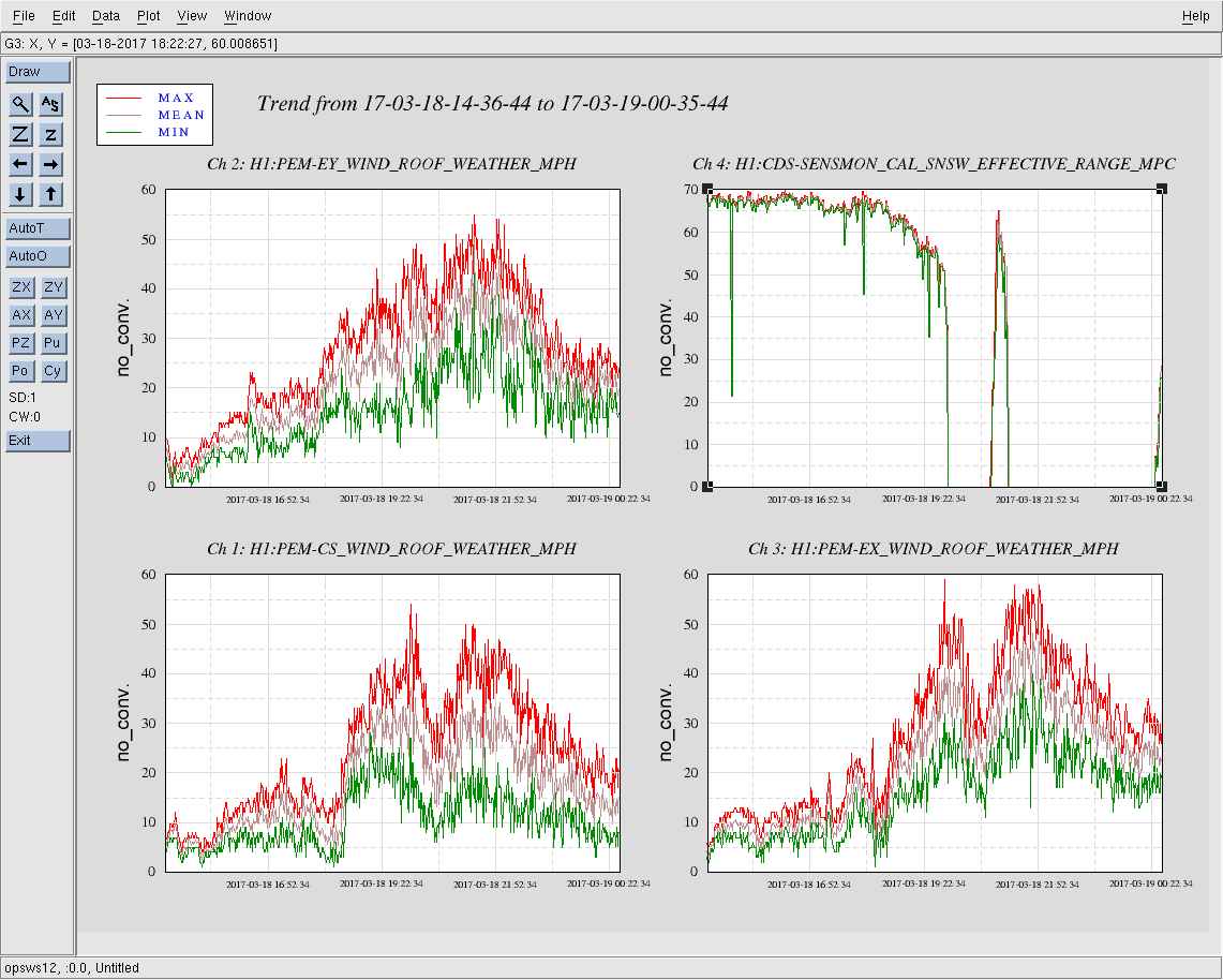
These are winds and the range for the last 10 hours, note that the range started suffering when winds hit 30 mph at the CS and EY. We didn't lose lock until we had an almost 60mph gust at EX.
TITLE: 03/18 Eve Shift: 23:00-07:00 UTC (16:00-00:00 PST), all times posted in UTC
STATE of H1: Wind
OUTGOING OPERATOR: Travis
CURRENT ENVIRONMENT:
    Wind: 35mph Gusts, 26mph 5min avg
    Primary useism: 0.26 μm/s
    Secondary useism: 0.24 μm/s
QUICK SUMMARY:

Jim W. is here and configuring SEI in response to the high winds.
TITLE: 03/18 Day Shift: 15:00-23:00 UTC (08:00-16:00 PST), all times posted in UTC
STATE of H1: Wind
INCOMING OPERATOR: Patrick
SHIFT SUMMARY: First half of the shift was good, but the second half was plagued by high winds. We had one short lock stretch during a lull in the winds, but the wind picked back up with even more ferocity. Gusts to ~60 mph for the last couple of hours. JimW is on site poking at ISI blends in hopes of helping combat the effects of the wind.
LOG: See previous aLogs.
Apparently wind is still an issue. After a brief lull, sustained winds are back above 40 mph.
Under such high sustained wind speeds (>40 mph), I would recommend switching the beam-direction rotation loops on Stage 1 ISIs to 90 mHz blends instead of the 250 mHz blends. This is not automated, I think, so you may have to do it by hand for each chamber: rX on ETMY, ITMY and rY on ETMX and ITMX. Jim and Rich had showed that this was helpful under high winds.
I texted Jim for some more advice related to Krishna's suggestion. He informed me that he is on his way to the site. I will wait for him to arrive before making any changes to the SEI configuration. Stay tuned.
No issues coming back up. Winds are still 30+ mph with a few 50 mph gusts, but we managed to get back to NLN. PI mode 23 has been giving a bunch of alarms since the winds started, but they quickly ring back down (on the order of seconds). Also have received a few Tidal X and Y error messages, but they don't seem to be affecting locking.
Lockloss likely due to high winds, which were gusting to 50 mph at the time of the lockloss.
Locked in Observing for 11.5 hours. Wind has picked up significantly since the beginning of the shift (now approaching 40mph) and the range has started to suffer as a result (~50 MPc). No issues otherwise.