Matt, Evan
We were perplexed by the steep slope of IMC F below 100 Hz, paticularly since it seemed to vary with PMC gain in the same way as the flat part of the spectrum above 1 kHz.
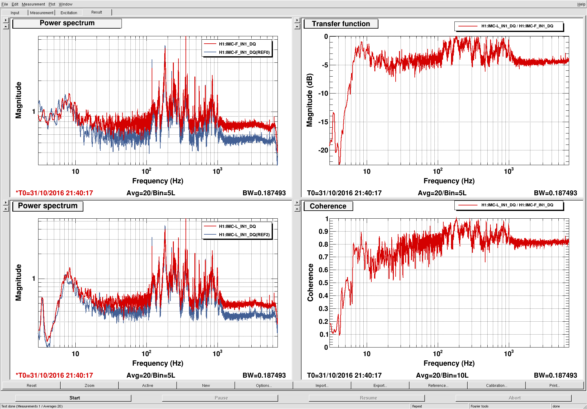
The attached plot shows the IN1 readbacks (i.e., no digital filtering or compensation applied) for IMC F and IMC L. Evidently, they seem to have the same spectral shape above 10 Hz. Since IMC L does not have any analog whitening, this would seem to indicate that IMC F readback has no analog whitening applied (despite what is implied by the schematic for the MC board).
However, the IMC F filter module (which produces the calibrated IMC frequency control channel that we've been using to estimate the IMC control noise) has a filter consisting of two 10 Hz / 100 Hz p/z pairs, as if to compensate for some kind of analog whitening.
What is actually stuffed into the analog whitening for the IMC F readback on the MC board?
[Also, we don't claim to understand why the TF is 0 dB at the peaks but -5 dB everywhere else.]