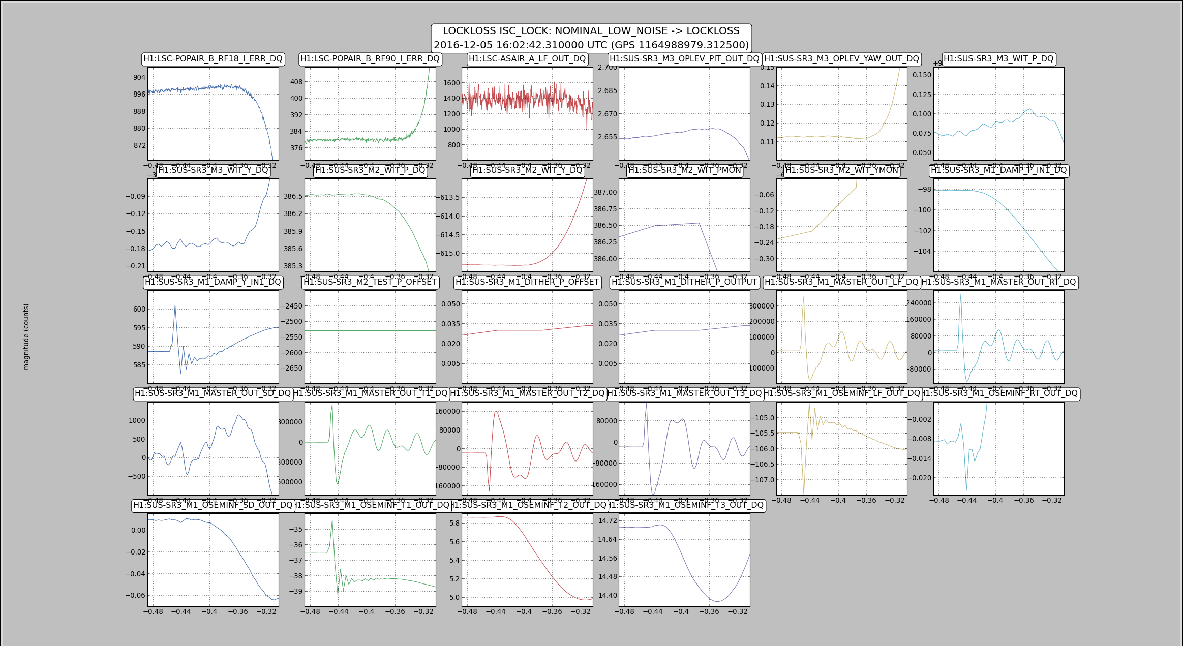
I used the lockloss2 script that automatically checks for sus saturations and plots them using the lockloss tool, and saw that one of the three locklosses (2016-12-05 16:02:42 UTC) in the last day or so was probably caused by a glitch on SR3. The attached screenshot shows the timeline, there is clearly a glitch on the top mass of SR3 about 0.2 seconds before the lockloss.
The dither outputs (which we use for the cage servo) don't show anything unual until after the lockloss, which means that this is not a cage servo problem. Looking at top mass OSEMINF LF and RT are the two that seem to have a glitch first, at about the same time.
I've added a lockloss template /ligo/home/ops/Templates/Locklosses/channels_to_look_at_SR3.txt for any operators who have an unexplained lockloss and want to check if it is simlar to this one.
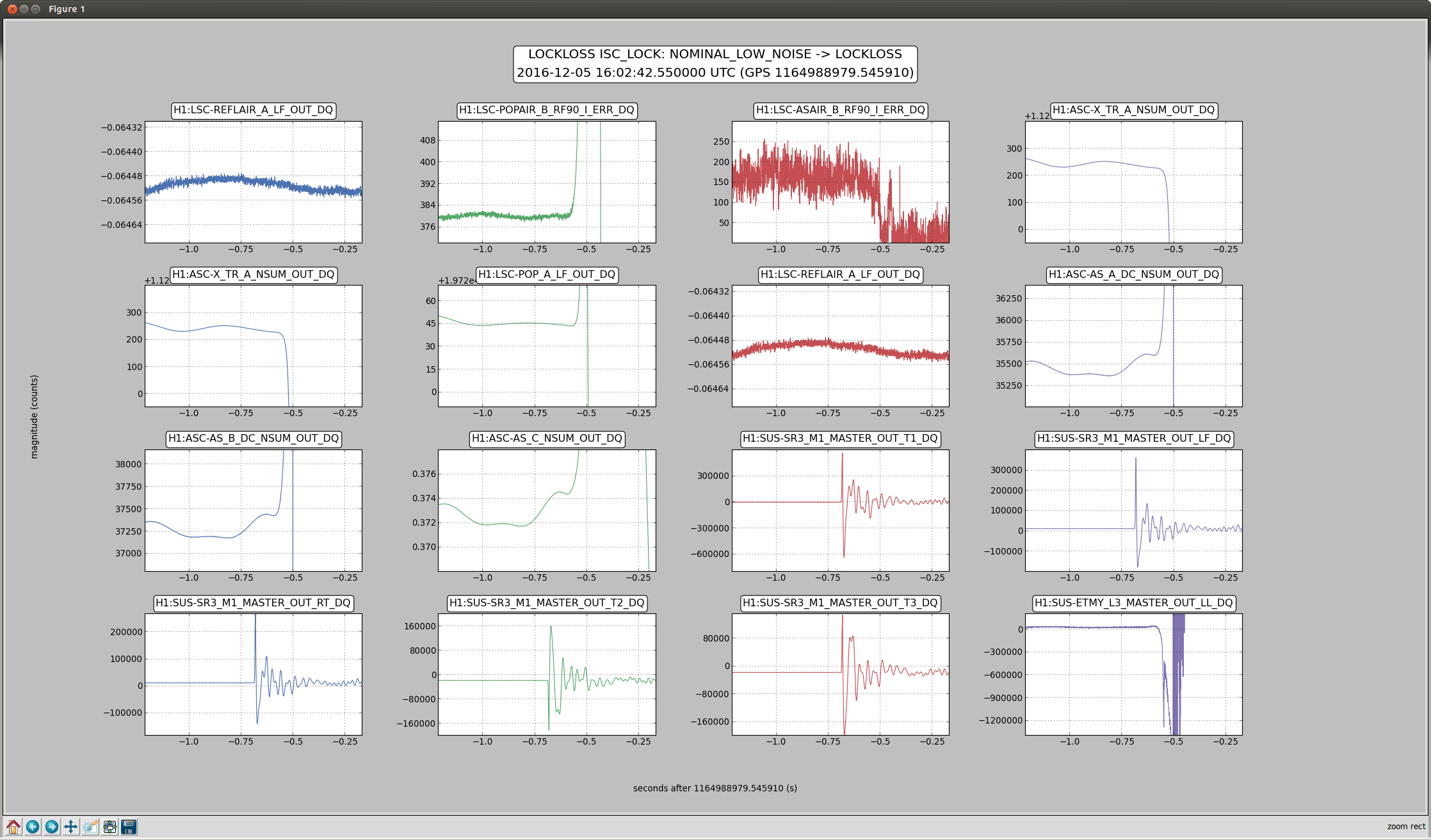
Sheila and I looked again at this particular lockloss (2016-12-06 10:05:39 UTC) and agree that the glitch that likely caused the lockloss are actually on the T1 and LF top stage OSEMs. These are indeed on the same set cabling, satellite amp, and driver run. See attached for updated lockloss plot this time with the OSEMINF channels. We'll keep watching locklosses to see if this happens more.