- H1 locked at NLN/Observing
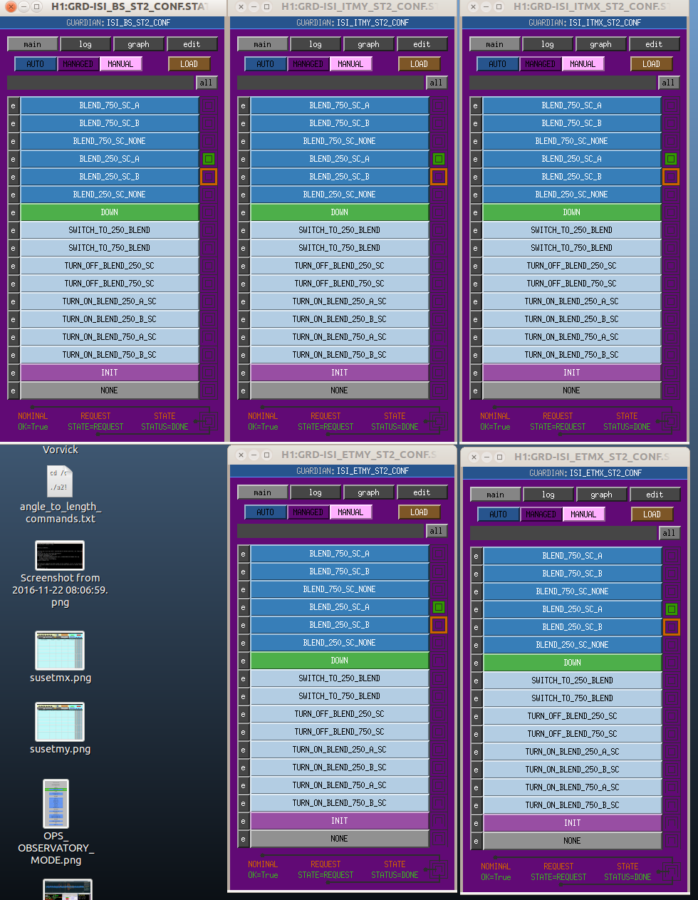
- All BSC are set to BLEND_250_SC_A
- EQ bands up around .07um/s. uSei is 1+um/s and holding steady for the last 6 hours or so.
- Winds are around 15-20mph gusting to 30+ at times
- LVEA dust monitors 6&10 and both PSL dust monitors have been sending alarms
- Trying Sei configurations stated in WP#6369
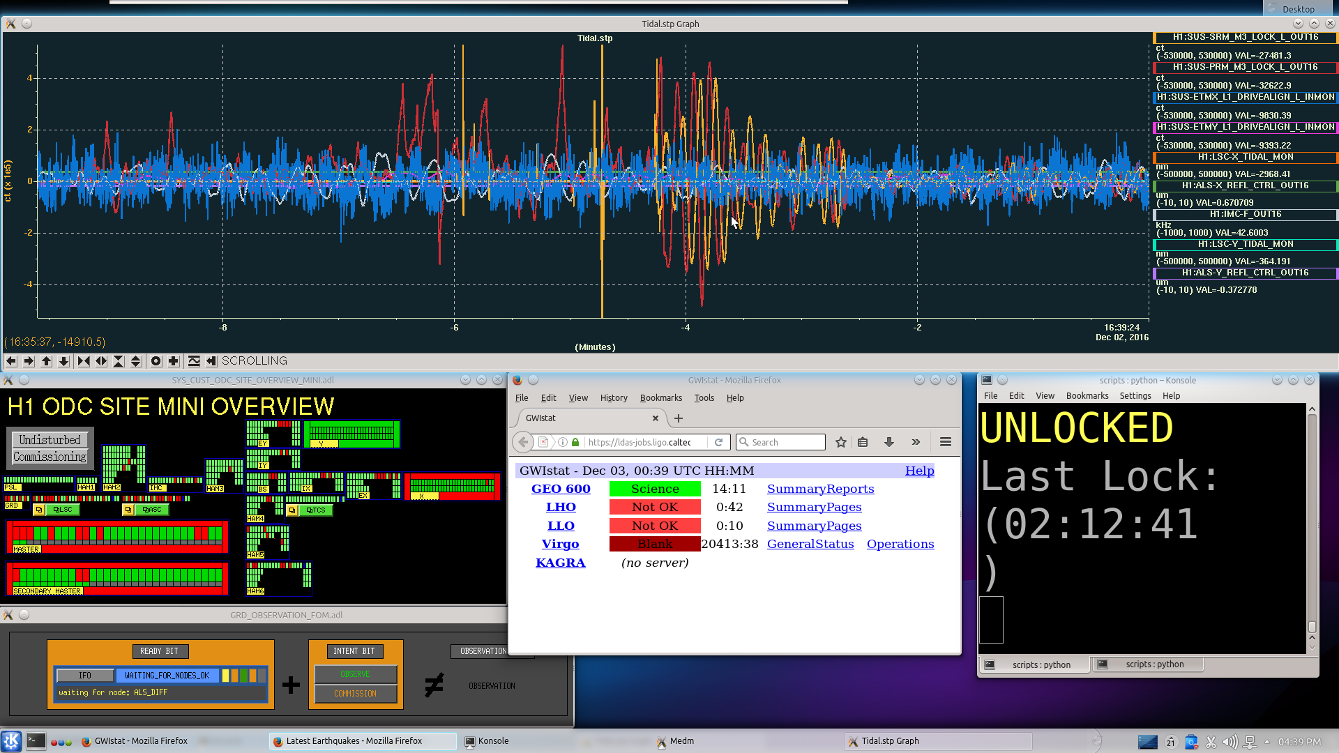
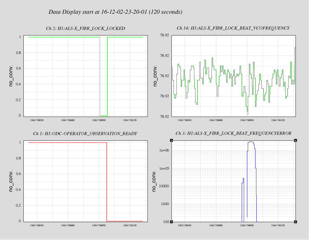
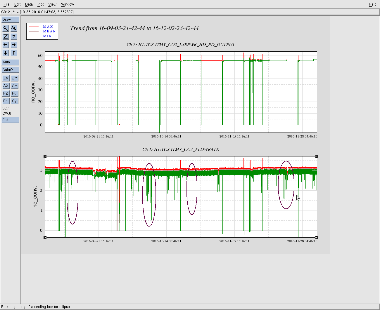
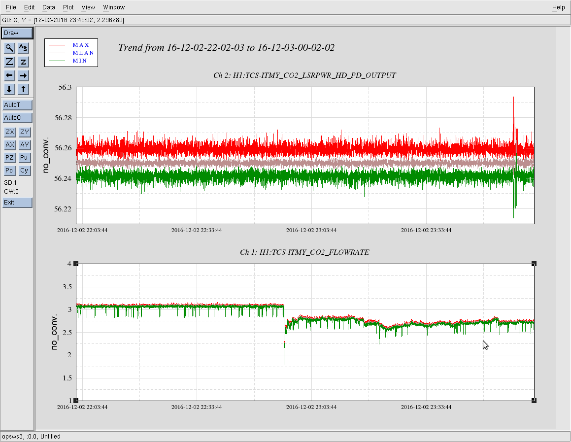
- 00:35UTC Since both IFOs were out of lock and µseism is at or above 1µm/s, Corey and I placed a phone call to Jim inquiring about trying the new sei configuration to see if it made any improvements as monitored in the Tidal StripTool. All BSC configs were switched from BLEND_250_SC_B to BLEND_250_SC_A. Tidal seemed to improve slightly as can be seen to the right hand side of the attached tidal image (the noisy bit in the middle can be ignored as it was irrelevant to the situation). These changes were made around the DRMI_LOCKED Guardian stage of locking. After some requisite BS aligning, the locked progressed to SWITCH_TO_QPDS and broke there. This is not an uncommon place for a lock to fail in my experience. Subsequent attempts at locking would end at FIND_IR with the guardian message "x-arm alignment bad not searching".
01:06UTC I reverted back to the original sei configuration for BSCs and locking attempts continue.
01:34UTC multiple locklosses at FIND_IR. Reverting back to new configs just to see if I can get past this stage.
01:50UTC New sei configs got me into DRMI land. MICH alignment looks pretty terrible. Trending witness sensors not revealing much. Going to try some alignment with INITIAL_ALIGNMENT guardian. Not going to do the arms if I can help it.
02:00UTC INITIAL_ALIGNMENT/INPUT_ALIGN not working. After trying to adjust the gain higher to get a lock I decided to trend(TimeMachine)IM4. I found it to be about 100urads out in pit. This seems to have corrected the issue. Perhaps this less-than-optimal pointing has been the sore spot in my locking efforts? Also had to put SR2 back to center before aligning SRC.
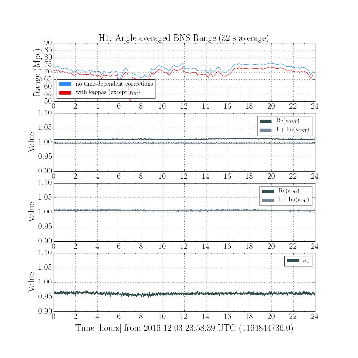
04:00UTC H1 Locked, Observing Range is ~72Mpc. Lock stretch so far: 01:08 coincidental with L1.