J. Kissel, S. Aston, P. Fritschel
Peter was browsing through the list of frame channels and noticed that there are some differences between H1 and L1 on PR2 (an HSTS), even after we've both gone through and made the effort to revamp our channel list -- see Integration Issue 6463, ECR E1600316, LHO aLOG 30844, and LLO aLOG 29091.
What difference he found is the result of the LHO-ONLY ECR E1400369 to increase the drive strength of the lower states *some* of the HSTSs. This requires the two sites to have a different front-end model library part for different types of the same suspension because the BIO control each stage is different depending on the number of drivers that have been modified;
At LHO the configuration is
Library Part Driver Configuration Optics
HSTS_MASTER.mdl No modified TACQ Drivers MC1, MC3
MC_MASTER.mdl M2 modified, M3 not modified MC2
RC_MASTER.mdl M2 and M3 modified PRM, PR2, SRM, SR2
At LLO, the configuration is
Library Part Driver Configuration Optics
HSTS_MASTER.mdl No modified TACQ Drivers MC1, MC3, PR2
MC_MASTER.mdl M2 modified, M3 not modified MC2, PRM, SR2, SRM
RC_MASTER.mdl M2 and M3 modified none
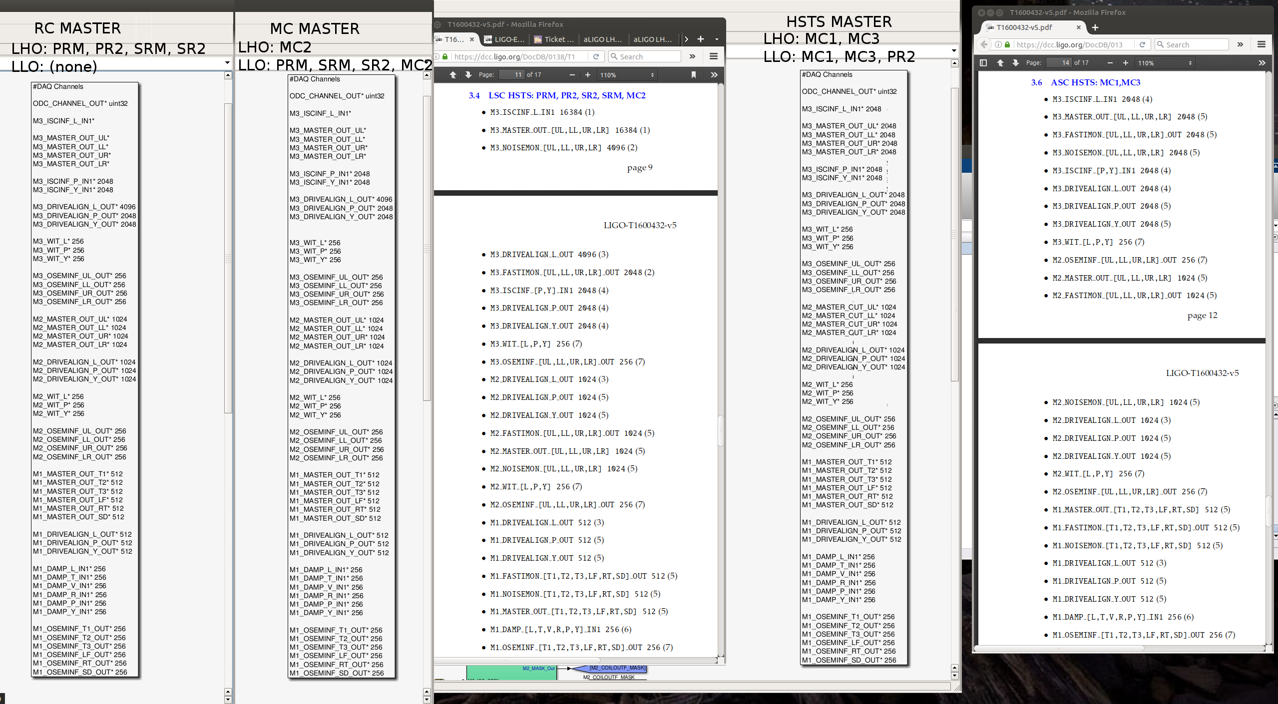
This model's DAQ channel list for the MC and RC masters is the same. The HSTS master is different, and slower, because these SUS are used for angular control only:
HSTS (Hz) MC or RC (Hz)
M3_ISCINF_L_IN1 2048 16384
M3_MASTER_OUT_UL 2048 16384
M3_MASTER_OUT_LL 2048 16384
M3_MASTER_OUT_UR 2048 16384
M3_MASTER_OUT_LR 2048 16384
M3_DRIVEALIGN_L_OUT 2048 4096
Since LLO's PR2 does not have any modifications to its TACQ drivers, it uses the HSTS_MASTER model, which means that PR2 alone is going to show up as a difference in the channel list between the sites that seemed odd Peter -- that L1 had 6 more 2048 Hz channels than H1. Sadly, it *is* used for longitudinal control, so LLO suffers the lack of stored frame rate.
In order to "fix" this difference, we'd have to create a new library part for LLO's PR2 alone that has the DAC channel list of an MC or RC master, but have the BIO control logic of an HSTS master (i.e. to operate M2 and M3 stages with an unmodified TACQ driver). That seems excessive given that we already have 3 different models due to differing site preferences (and maybe range needs), so I propose we leave things as is, unless there's dire need to compare the high frequency drive signals to the M3 stage of PR2 at LLO.
I attach a screenshot that compares the DAQ channel lists for the three library parts, and the two types of control needs as defined by T1600432.