Jenne, Sheila Keita
We had another instance of a jump in POP90, in which both the I and Q phases increased. We think this is a problem with the readback, similar to what is described in 31181.
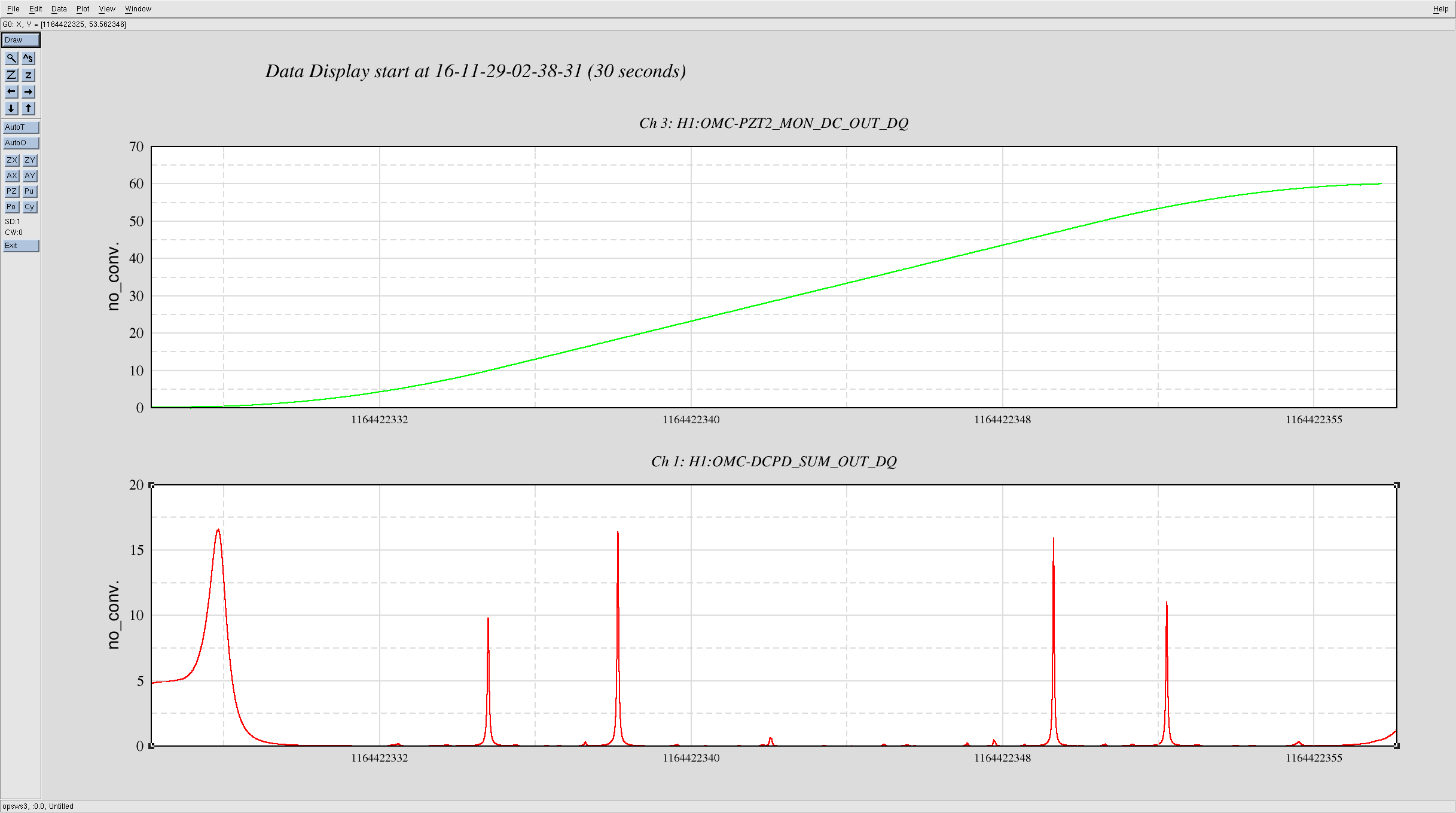
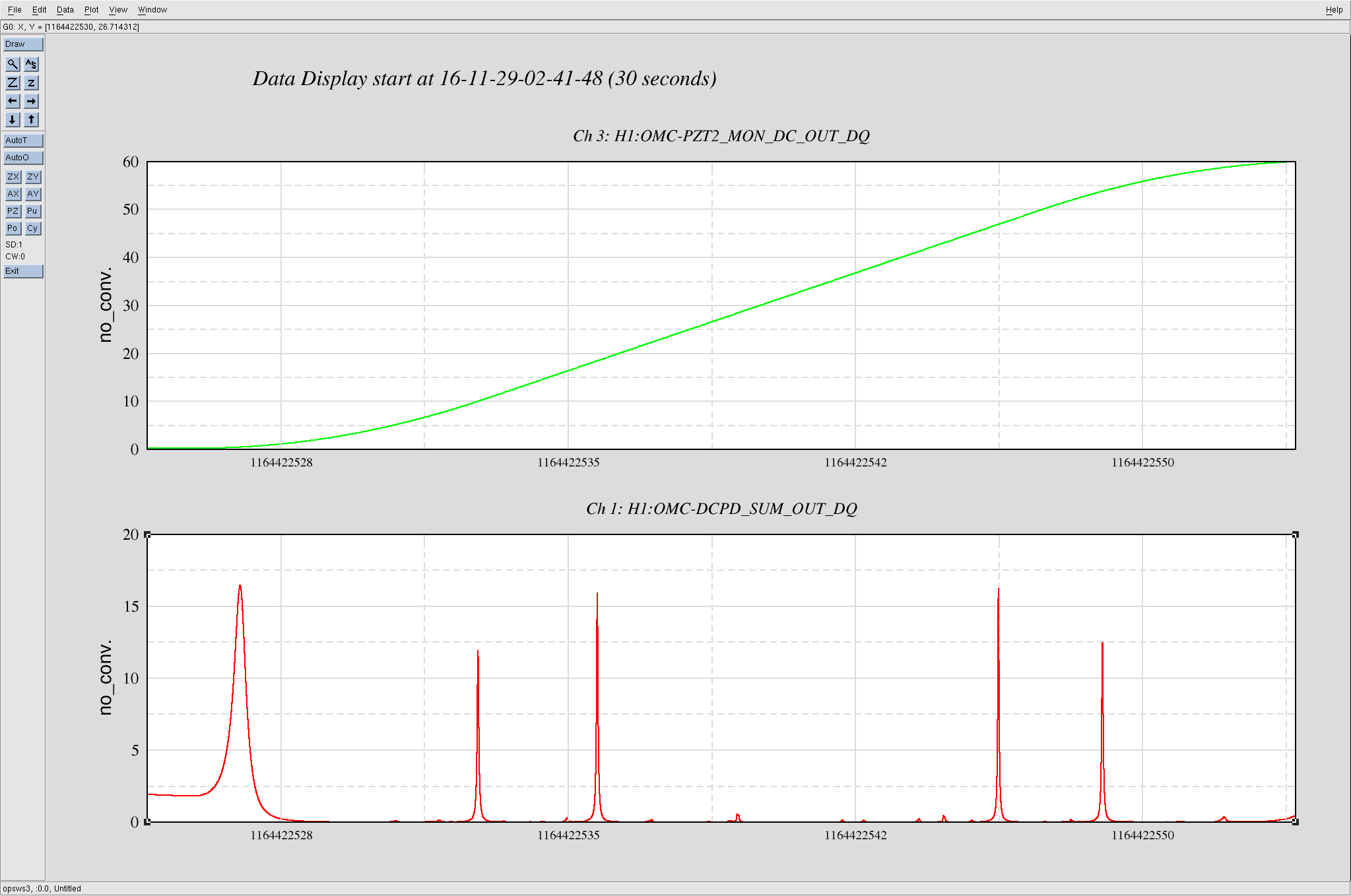
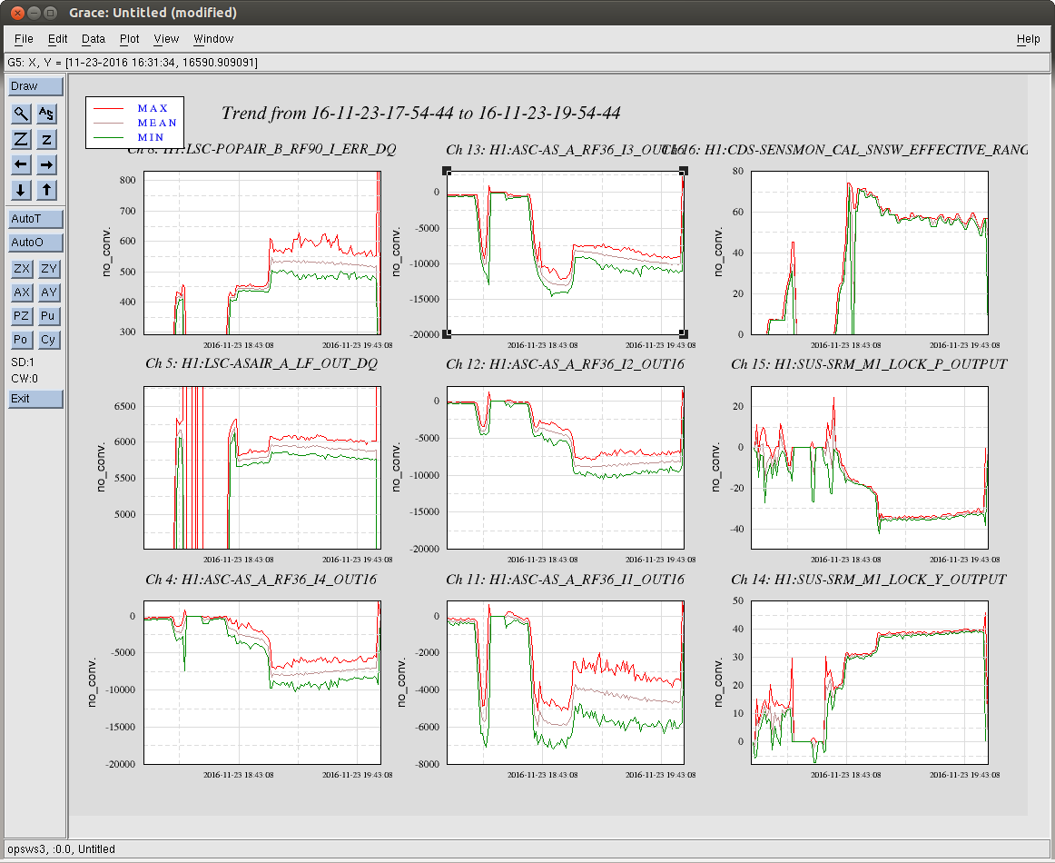
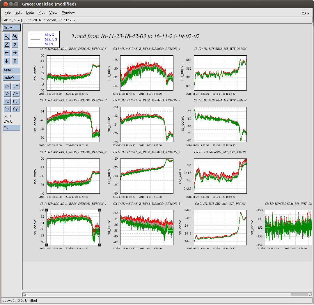
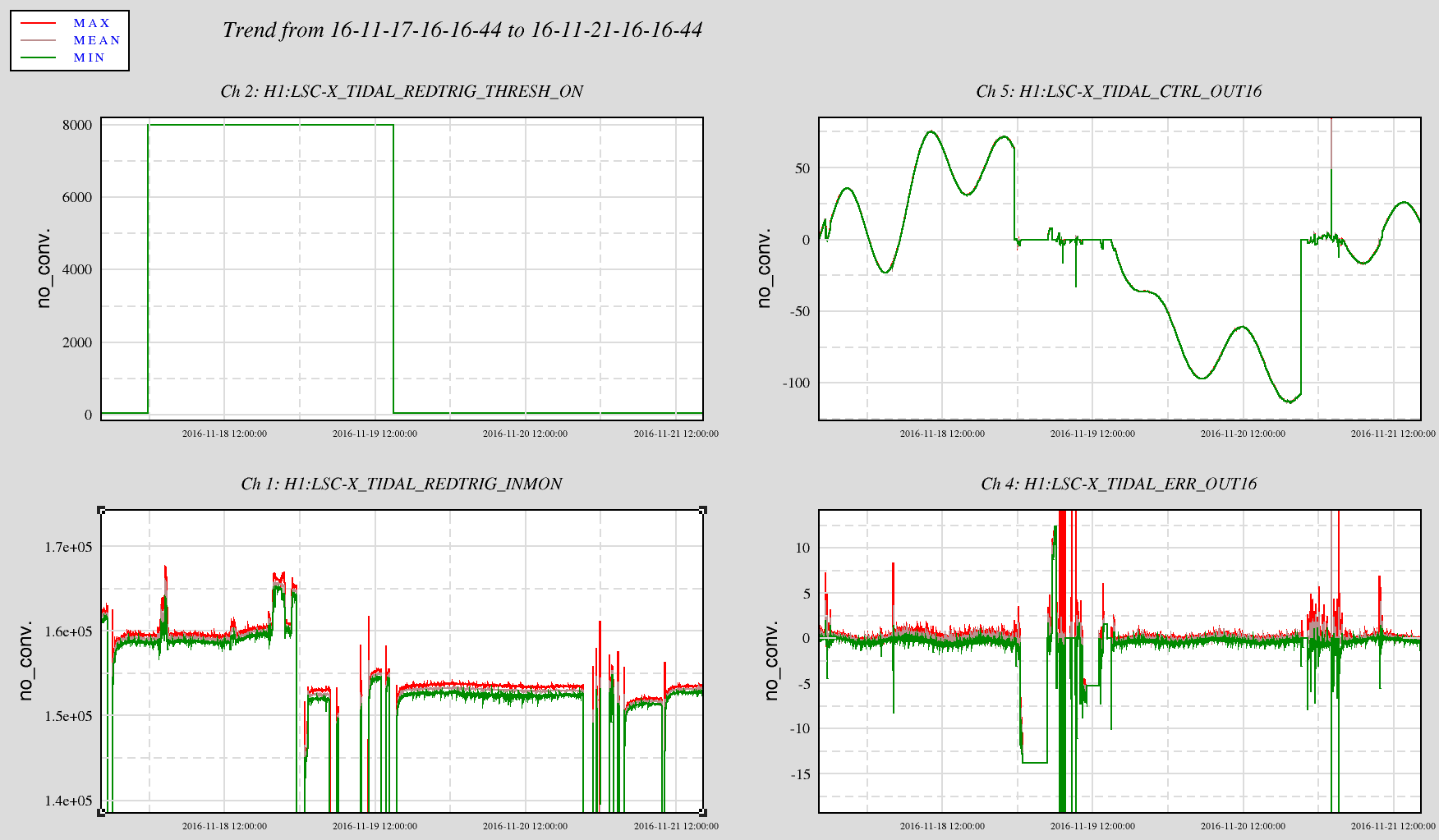
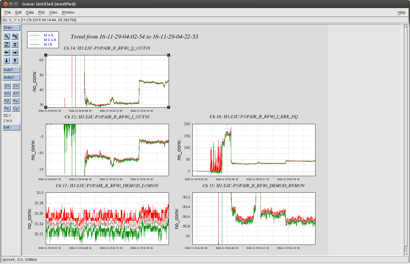
We were acquiring lock, and had no ASC running on the SRC. We looked at witness sensors for all the interferometer optics, and it looks like none of them moved at the time. We also don't see changes in other RF sensors, like AS36, AS90, or POP18. We looked at both quadratures of POP90 before rotation and it seems to have both a phase shift and a 3.5 dB increase in the sum of I+Q. The RFmon and LO mon on the demod don't have any jumps nearly that large, so if it is a problem in the demod it is probably downstream of the directional coupler for the RFmon.
This seems not to be the same as the jumps in SRC alingment that started after last tuesday's maintence, (31804 31865 and other alogs), but since the symptom is very similar it would make debugging the other problem easier if this issue could be fixed. Since we use POP90 for a dither lock of the SRM angle durring lock acquisition, this can cause a lockloss if it happens while we are trying to lock.
I tested the chassis that was pulled out (S1000977). During the testing I did not see any level changes
or glitches in either the I or Q channel outputs, except when a pair of cables to attached to the front
panels via a BNC tee were strongly wiggled. Removal of the tee and wiggling the cables directly didn't
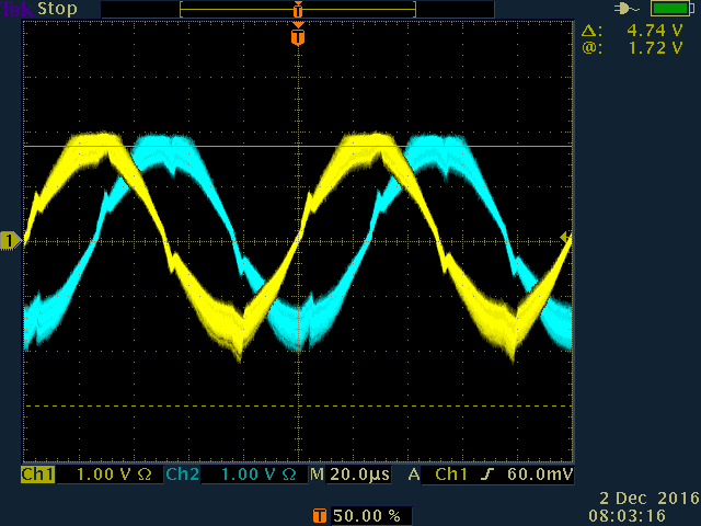
induce any changes. Attached is an oscilloscope trace of the I&Q monitor output for the POP90 channel.
It is fuzzy because of an RF amplitude modulation I was applying, however the distortion discontinuities
are present with the modulation off.
Daniel pointed out to me that the distortion is due to my not looking at the signal
differentially on the oscilloscope. Sure enough it looks a lot cleaner when processed differentially.
I did however notice that if the RF input is more than -11 dBm, the monitor signals on the rear panel are
saturated/distorted.
The only other output level changed that was observed was when the chassis was turned off in the
evening and back on again the following morning.
The chassis (strictly) failed the following tests:
- front panel monitor coupling factors (all channels at 100 MHz, failed by less than 1 dB)
- IF beat note amplitude versus frequency (all channels, I & Q, at 100 kHz, failed by as little as 50 mV
and as much as 360 mV)
- IF output noise level (channel 3, I & Q, failed by as little as 3 dB and as much as 4 dB). Channel 3
is labelled as REFLAIR_27.
By any chance when the chassis was in the rack, was there more than one cable attached to the (one)
front panel BNC connector?