Unfortunate turn of events considering the trouble I'm having.
Appears to be a general problem with the authentication system across the Lab/LSC this morning, not just the Ops wiki server.
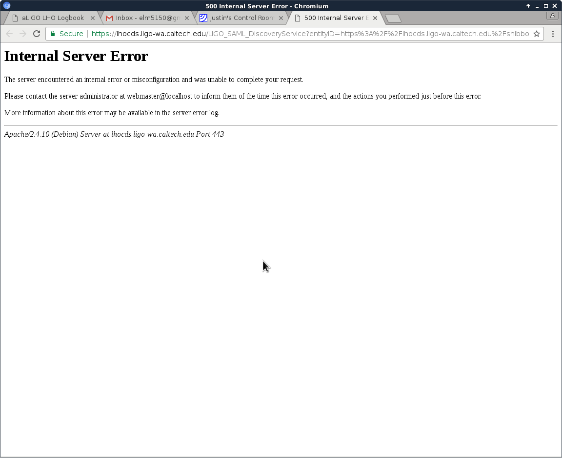
LIGO-SAML-DS, which finds authentication servers, is unhappy with some very recent metadata changes (example from an affected GC server):
2017-01-14 07:51:56,396 ERROR Metadata signature cannot be verified: xmlsec1 returned non-zero code 1
If you (or CDS admins) need a workaround in the mean time while the central system is worked on, give me a call.
here are the recent ssl_error logs from cdswiki when I try to open the web service
[Sat Jan 14 09:59:00.588103 2017] [wsgi:error] [pid 23984:tid 140688044332800] [remote 71.84.186.186:38281] mod_wsgi (pid=23984): Exception occurred processing WSGI script '/usr/lib/cgi-bin/wsgi/ligo-saml-discovery-service/LIGO_SAML_DiscoveryService.wsgi'.
[Sat Jan 14 09:59:00.588145 2017] [wsgi:error] [pid 23984:tid 140688044332800] [remote 71.84.186.186:38281] Traceback (most recent call last):
[Sat Jan 14 09:59:00.588170 2017] [wsgi:error] [pid 23984:tid 140688044332800] [remote 71.84.186.186:38281] File "/usr/lib/cgi-bin/wsgi/ligo-saml-discovery-service/LIGO_SAML_DiscoveryService.wsgi", line 212, in application
[Sat Jan 14 09:59:00.588206 2017] [wsgi:error] [pid 23984:tid 140688044332800] [remote 71.84.186.186:38281] if returnURL.split('?')[0] in spDict[entityIDclaimed]:
[Sat Jan 14 09:59:00.588234 2017] [wsgi:error] [pid 23984:tid 140688044332800] [remote 71.84.186.186:38281] KeyError: 'https://lhocds.ligo-wa.caltech.edu/shibboleth-sp'