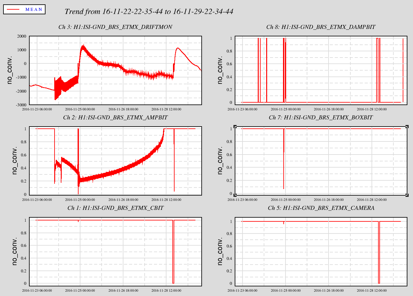
I see now Jim had already plotted most of these yesterday but since I had already wrote this log, I thought i should post it anyway. My explainations and plots are better anyway.
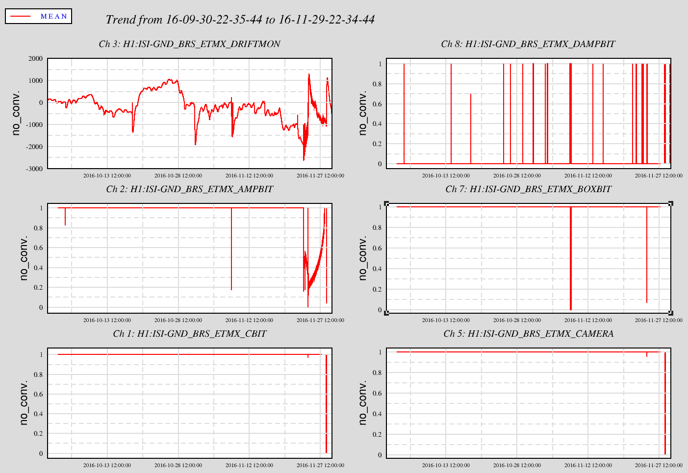
The two attached plots show 2 months and 7 days of a number of the status channels from the BRS for diagnosis. On the 7 day plot, the large steps up on the DRIFTMON (upper left) are when Jim opened the BRS box on Thursday and when I opened it yesterday--this is a thermal step and recovery.
The CBIT indicates if the C# code is running. This code reads the camera light image.
The AMPBIT is an indication of the BRS Beam swing amplitude--looking at the 60 day image indicates the PEM crew really got the beam disturbed as it has not been in the past 60 days until last Wednesday. Jim plots 90 days and shows this happened ~21 Sept but things did not get out of whack as it did last Wednesday.
The drop outs (to zero) of the CBIT and CAMERA channels are indications of stopping the code as we attempt to get it running again.
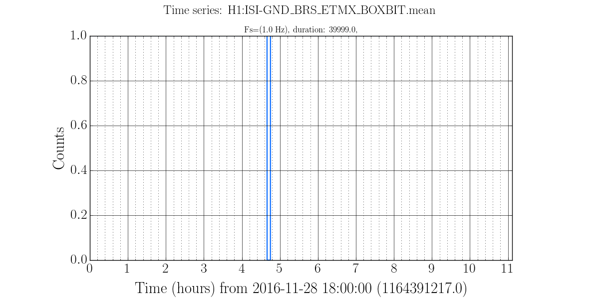
The BOXBIT logics from 1 when the Beckoff communications to the BRS box are disrupted. Not sure why it occurred for Jim and on 8 Nov (no log spotted) but not for me yesterday.
The DAMPBIT just indicates the set point enabled damping has kicked on.
The LIGHTSRC and MODBIT are not included in these plots as they were unity for the duration indicating the light source has been fine and the ISI is communicating without problem. I expected to see a DRIFT_BIT channel but it remained ellusive.
Tagging (hopefully) Ops, so operators see this. An FRS ticket (6799) has been submitted.
Thanks Hugh, Jim, this is very helpful.
The CBIT dropping for short periods is normal. It indicates a slowdown in C# data processing due to extra cpu usage - usually because of a remote login.
The AMPBIT being low is simply showing the problem that the amplitude is large. This is an 'effect' and not the 'cause'. Other bits are similarly not showing anything unexpected.
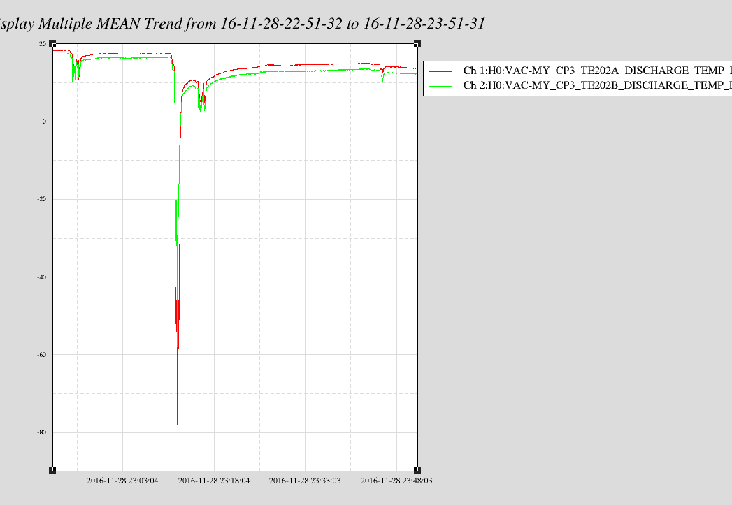
The main problem is the BOXBIT which drops on Nov. 8th, where surprisingly it did no harm. On Nov. 25th, it dropped and I suspect this is what led to the encoder values being corrupted. After yesterday's fix, Hugh told me that the values were corrupted again and I checked the BOXBIT and I see another drop yesterday evening (see attached pic). I suspect that either the power supply going out to the BRS enclosure being intermittent, or the ethernet cable to the box being loose, is the problem. Or the Beckhoff motor controller may be failing and may need to be replaced.
If the encoder values are corrupt, the BRS-X damper may not work and people should avoid going close to BRS-X while it is being used tonight.