This afternoon Annamaria and I looked again at changing alignments.
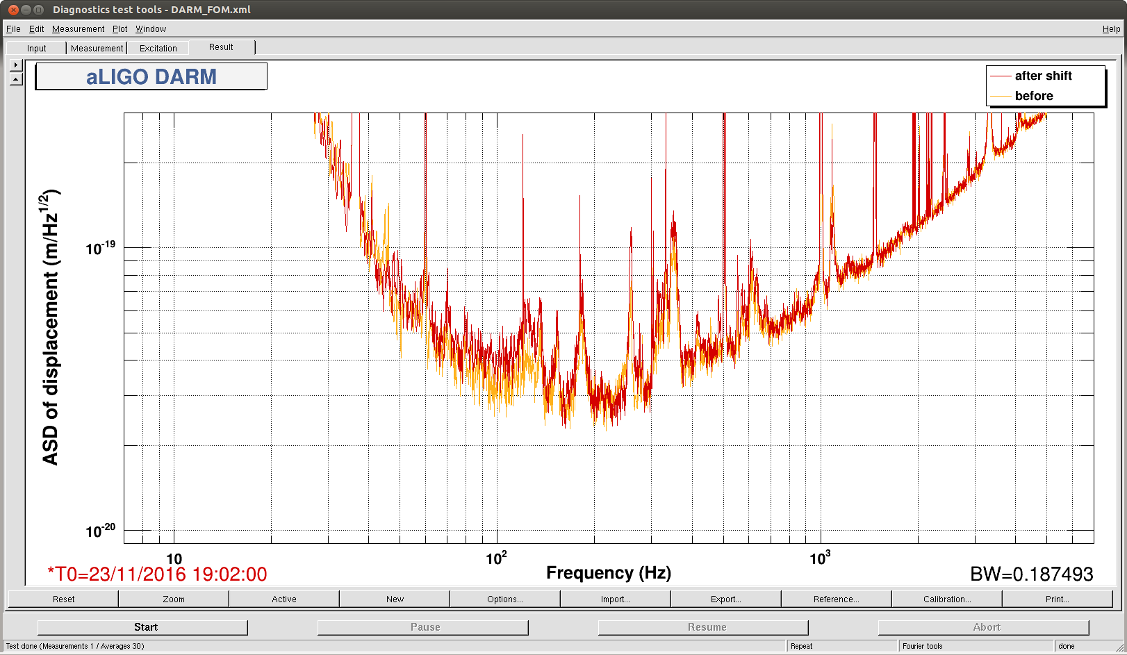
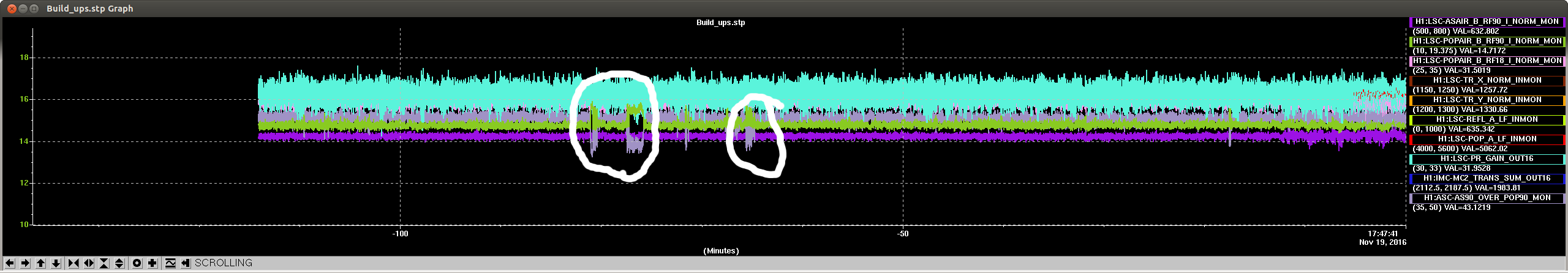
We tried again moving the PR3 spot position back towards where I had it last night, and saw that this still improves the noise in DARM and the range although the power recycling gain drops to almost 29.
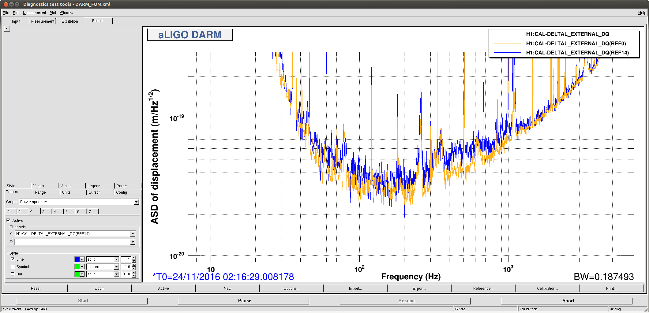
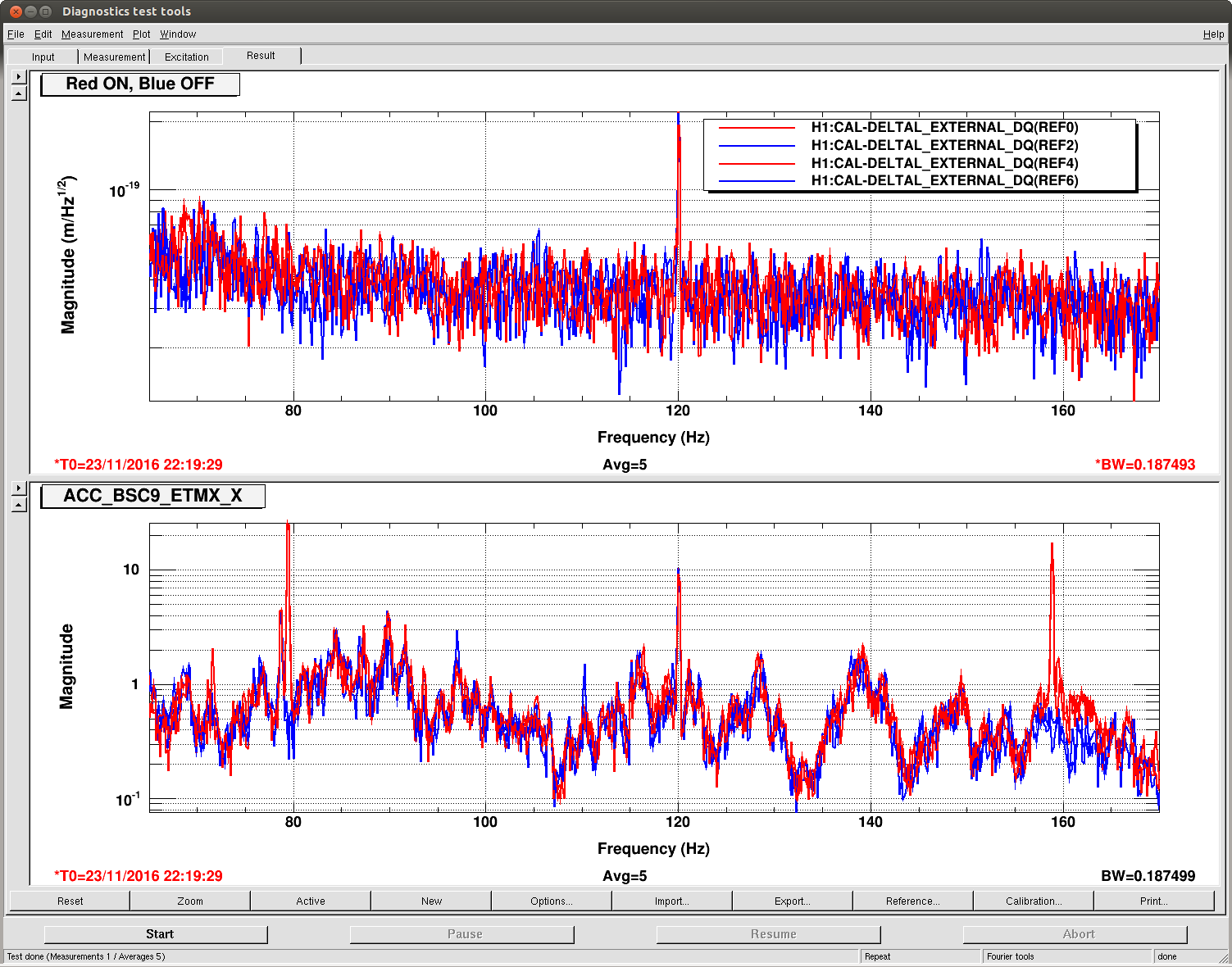
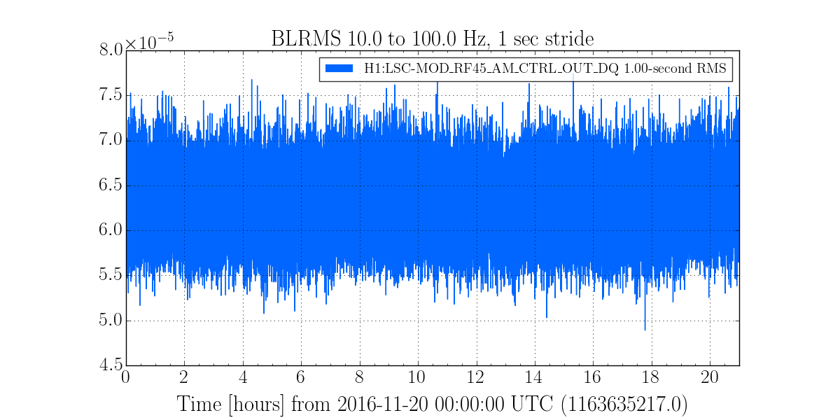
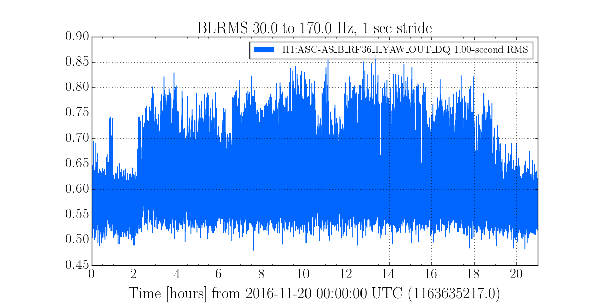
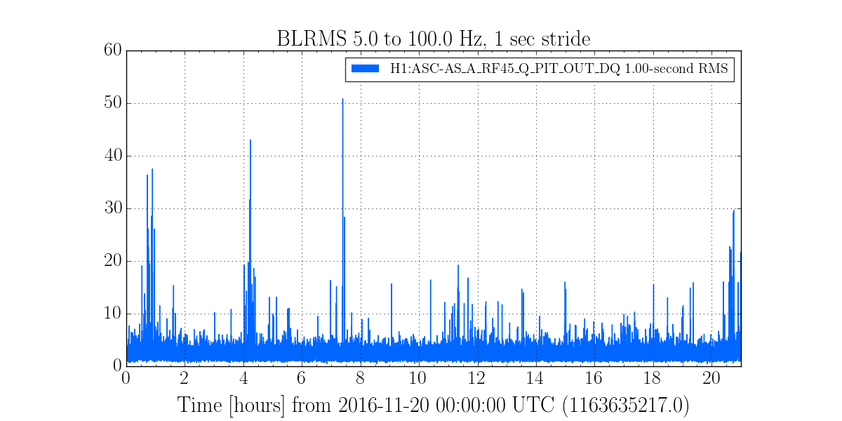
We then tried exploring alingment of IM3, and moved it by 2000urad in pitch. We saw the power recycling gain increase from about 32 to 32.3 at best, this alingment was with the PR3 spot in the bad jitter noise location and the IM3 pitch alignment slider at 27940. We were able to make the jitter noise worse by moving IM3 in yaw, but not to make it better. The attached screenshot shows the extremes of the noise in the bucket while we were moving things around.
We reverted the IM3 alignment and I was going back to the lower noise PR3 spot position when I moved to quickly and broke the lock.