The results of cdsutils.avg() in guardian is sometimes giving us very weird values.
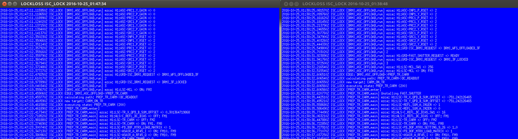
We use this function to measure the offset value of the trans QPDs in Prep_TR_CARM. At one point, the result of the average gave the same (wrong) value for both the X and Y QPDs, to within 9 decimal places (right side of screenshot, about halfway down). Obviously this isn't right, but the fact that the values are identical will hopefully help track down what happened.
The next lock, it correctly got a value for the TransX (left side of screenshot, about halfway down), but didn't write a value for the TransY QPD, which indicates that it was trying to write the exact same value that was already there (epics writes aren't logged if they don't change the value).
So, why did 3 different cdsutils averages all return a value of 751.242126465?
This isn't the first time that this has happened. Stefan recalls at least one time from over the weekend, and I know Cheryl and I found this sometime last week.