corey.gray@LIGO.ORG - posted 16:34, Sunday 30 October 2016 (31010)
Ops Day Shift Summary
TITLE: 10/30 Day Shift: 15:00-23:00 UTC (08:00-16:00 PST), all times posted in UTC
STATE of H1: Commissioning
INCOMING OPERATOR: Jim
SHIFT SUMMARY:
Robert had H1 for a good chunk of the day & Jenne had it for a lock or two. Other than that, just working on keeping H1 up for commissioners.
LOG:
- 16:20 Robert out in LVEA for measurements/injections/etc.
- 17:04 Took TCSx from 0.2 [set by GRD] to 0.4W. (TCSy remains at 0.0W)
- 17:07 Rebooted video4 since it froze
- ~17:30 Happened to notice RED Terramon EQ from Calif. Took seismic up to 0.3. I noticed Terramon a few minutes after the peak already passed. I reckon if I noticed Terramon earlier, I could have tried EARTH_QUAKE_V2. Oh well, next time.
- 18:25 PI Mode18 rung up. Took phase from 160 eventually down to about -30.
- 18:40 Lockloss
- 18:45-20:02 Unlocked investigations by Robert
- 20:02-20:30 H1 at Nominal Low Noise & Jenne taking over
- Had a few locklosses toward the end of the shift, but overall H1 has been fairly reliable getting back to NLN.
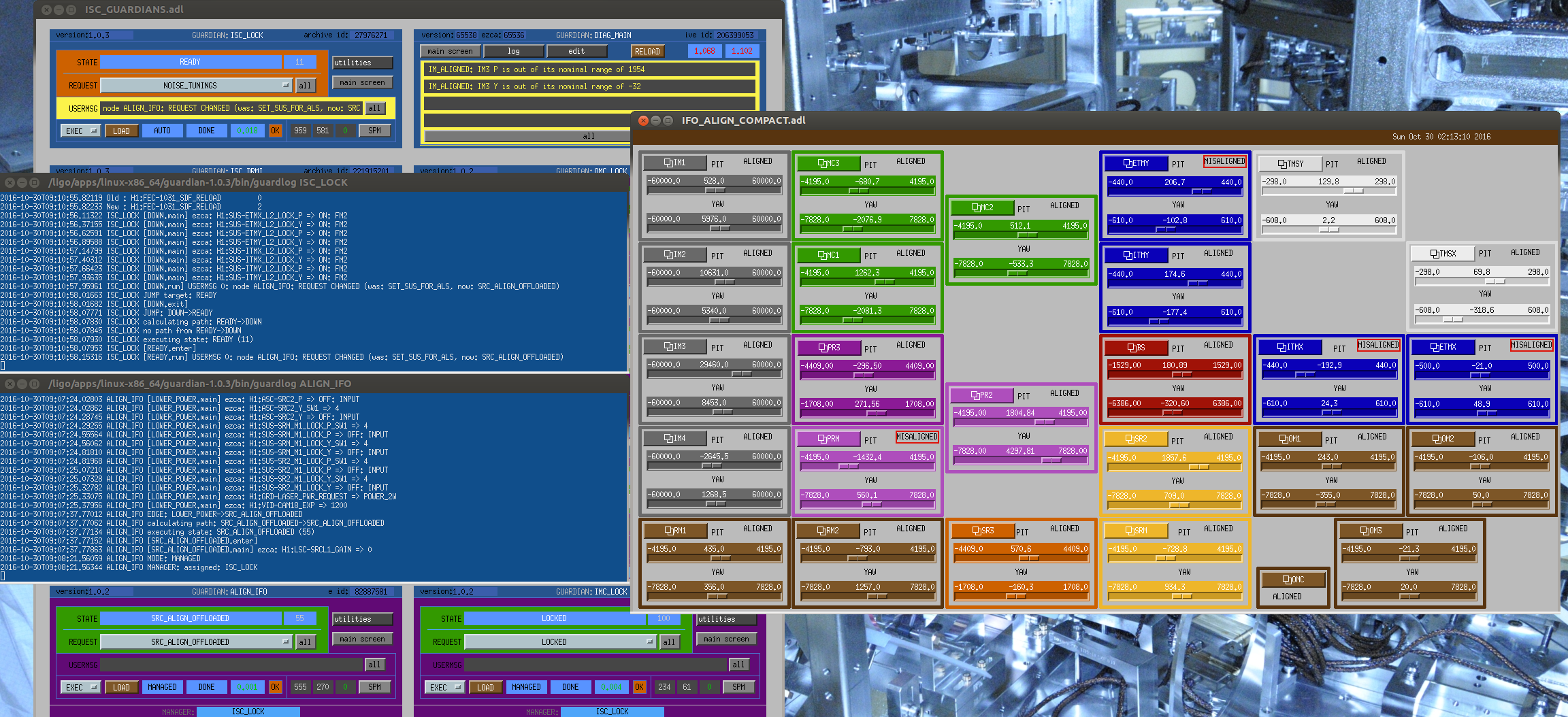
Taking IMC to MISALIGNING state so Robert can do some non-locked measurements.
To prevent splashing of light,
no fibers shutters, EY swapped, see alog 30624.