gabriele.vajente@LIGO.ORG - posted 15:44, Saturday 08 October 2016 - last comment - 15:50, Saturday 08 October 2016(30332)
BruCo scan
A scan of coherences during last night's lock can be found here:
https://ldas-jobs.ligo.caltech.edu/~gabriele.vajente/bruco_1159948817/
Nothing new:
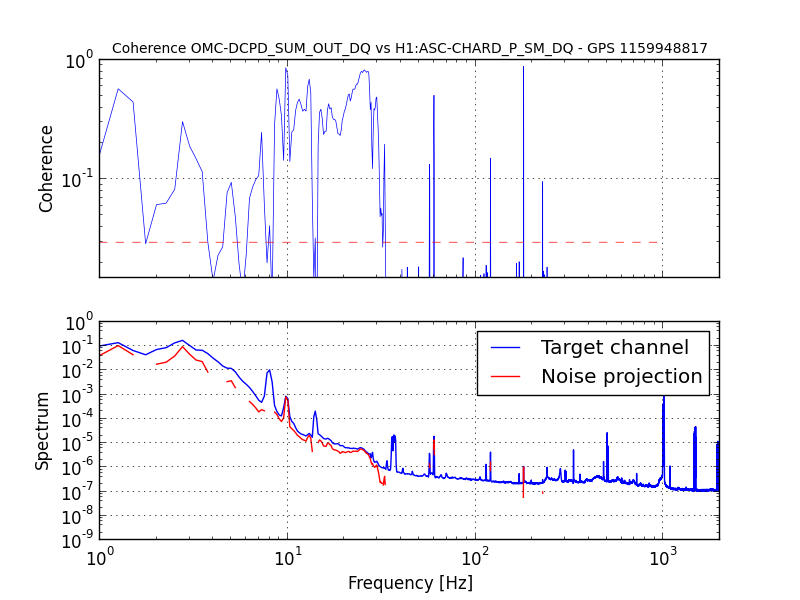
- The low frequency seems dominated by ASC-CHARD_P
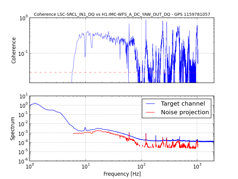
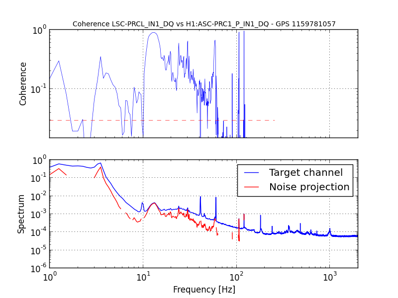
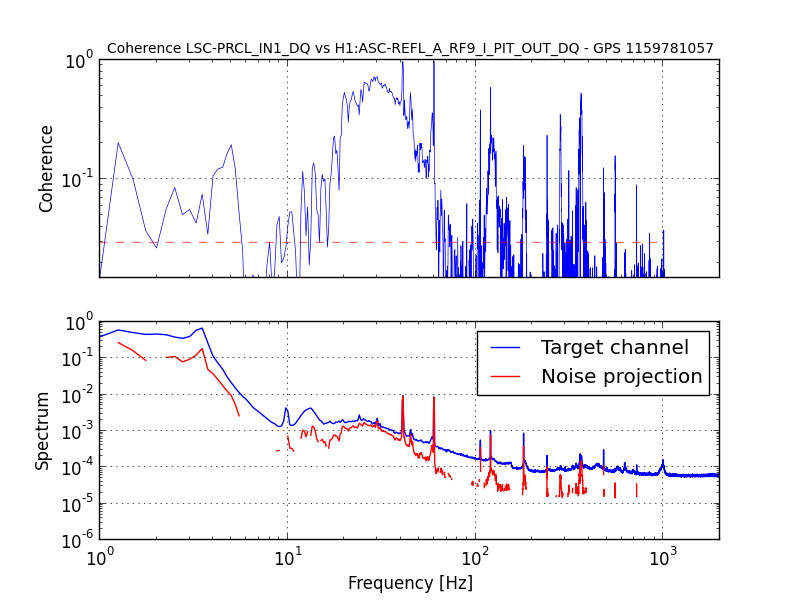
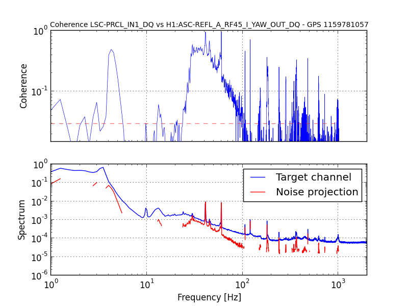
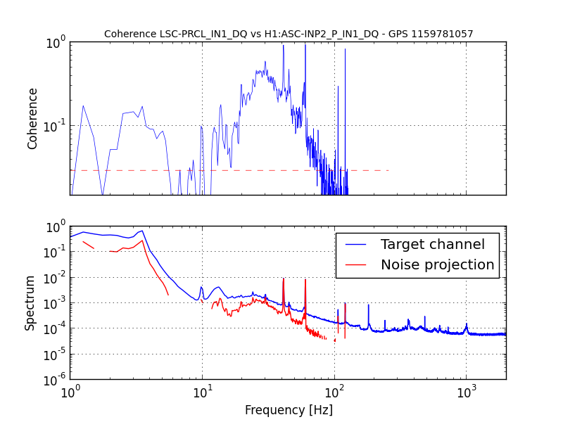
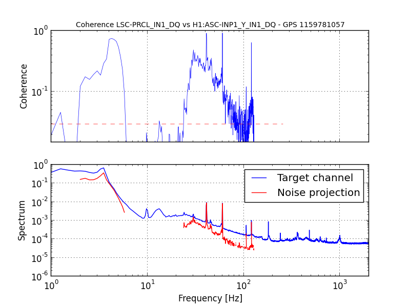
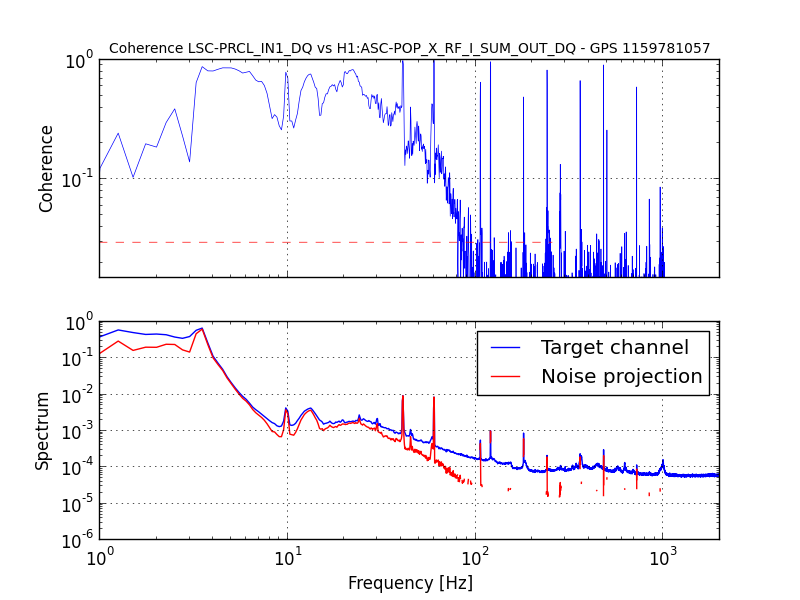
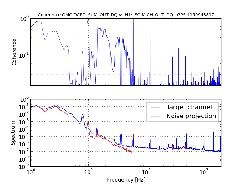
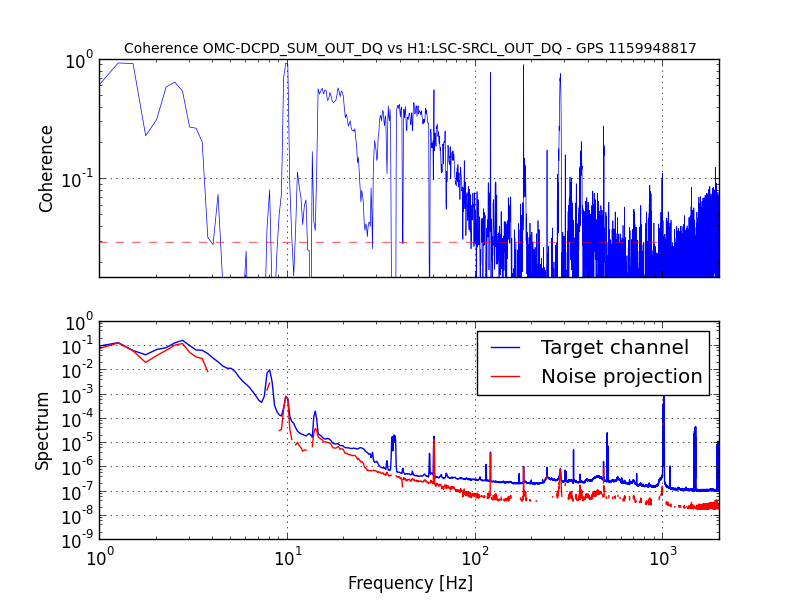
- MICH/SRCL/PRCL are still very high
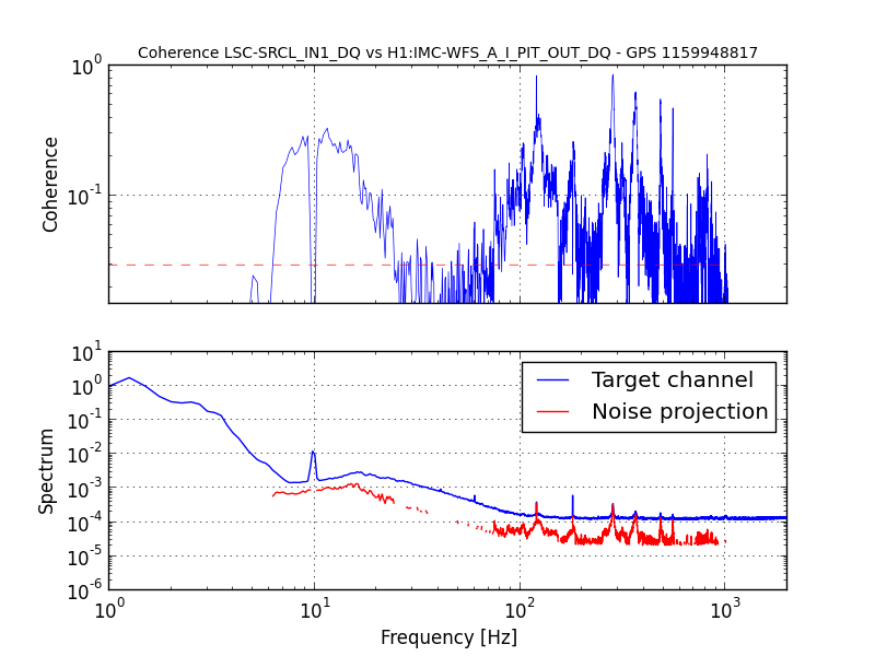
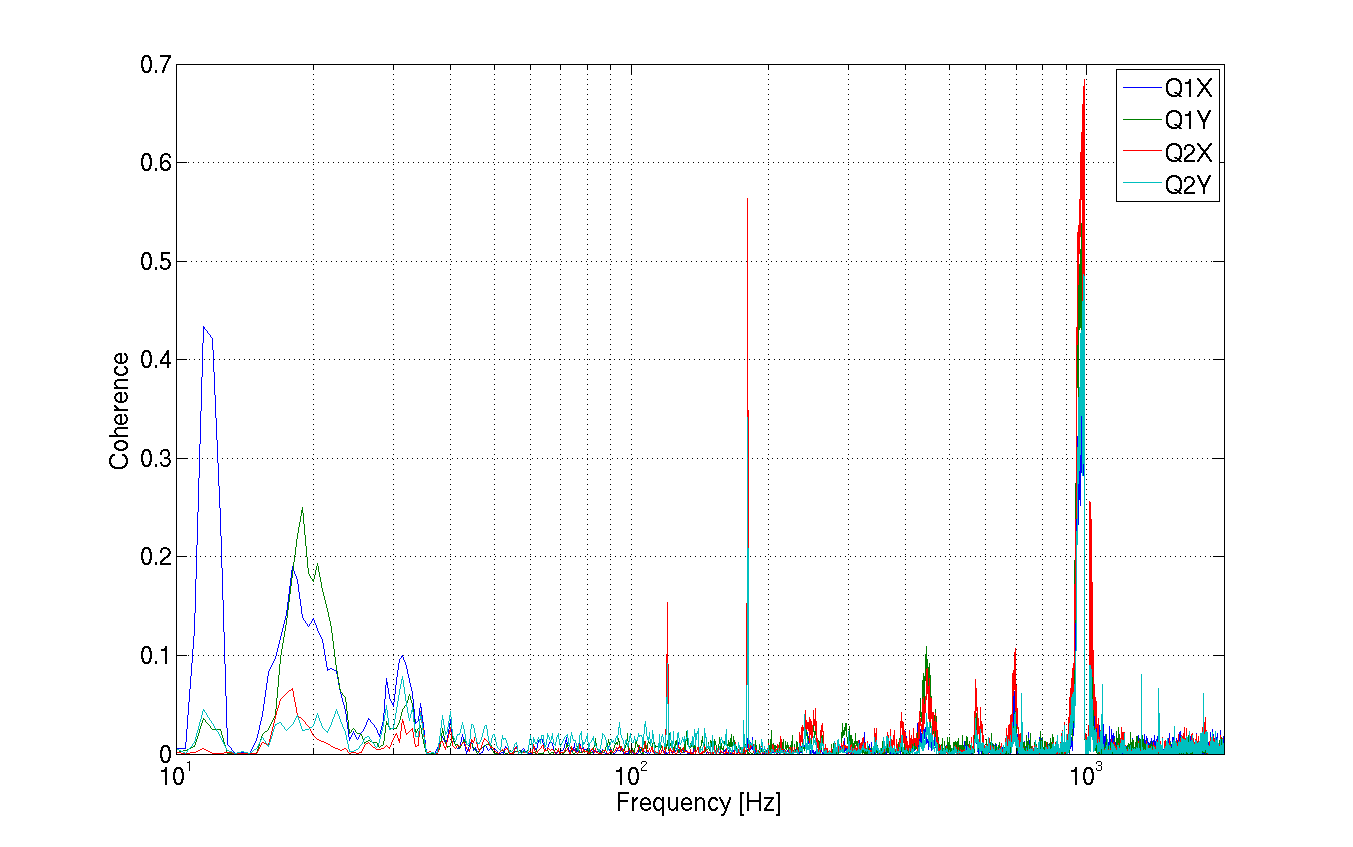
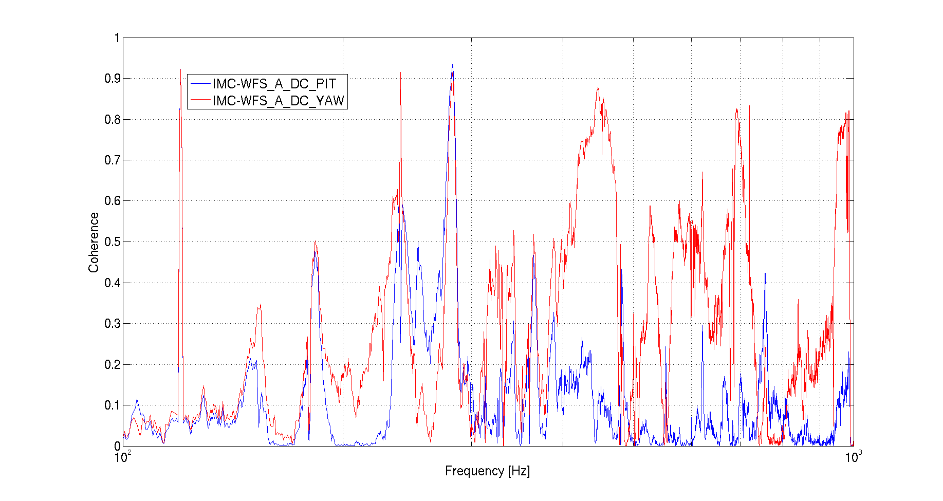
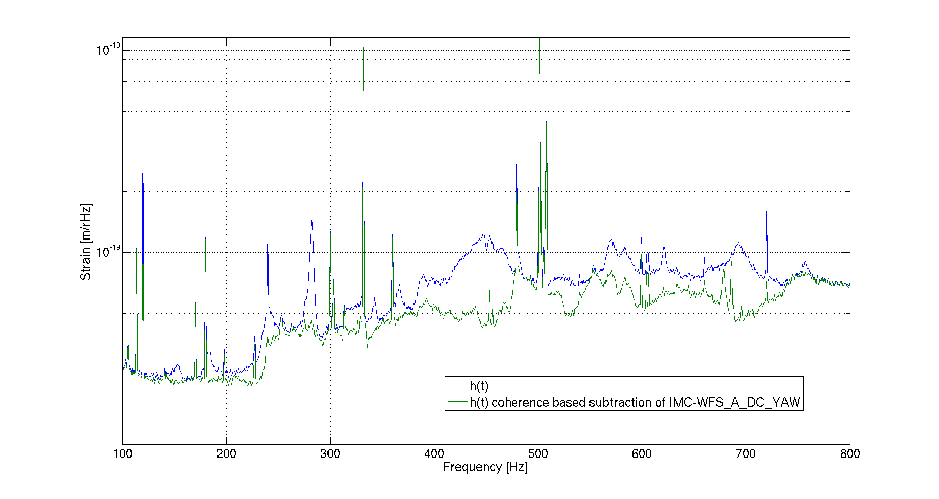
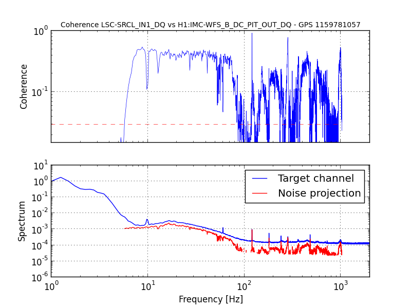
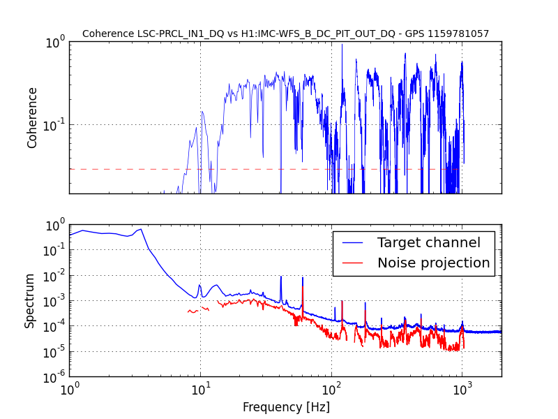
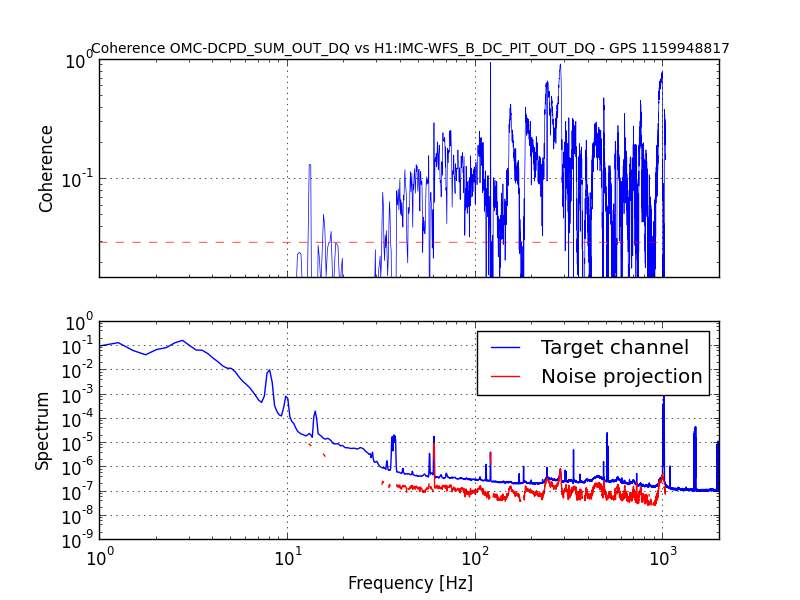
- Jitter is still visible in the IMC WFS signals
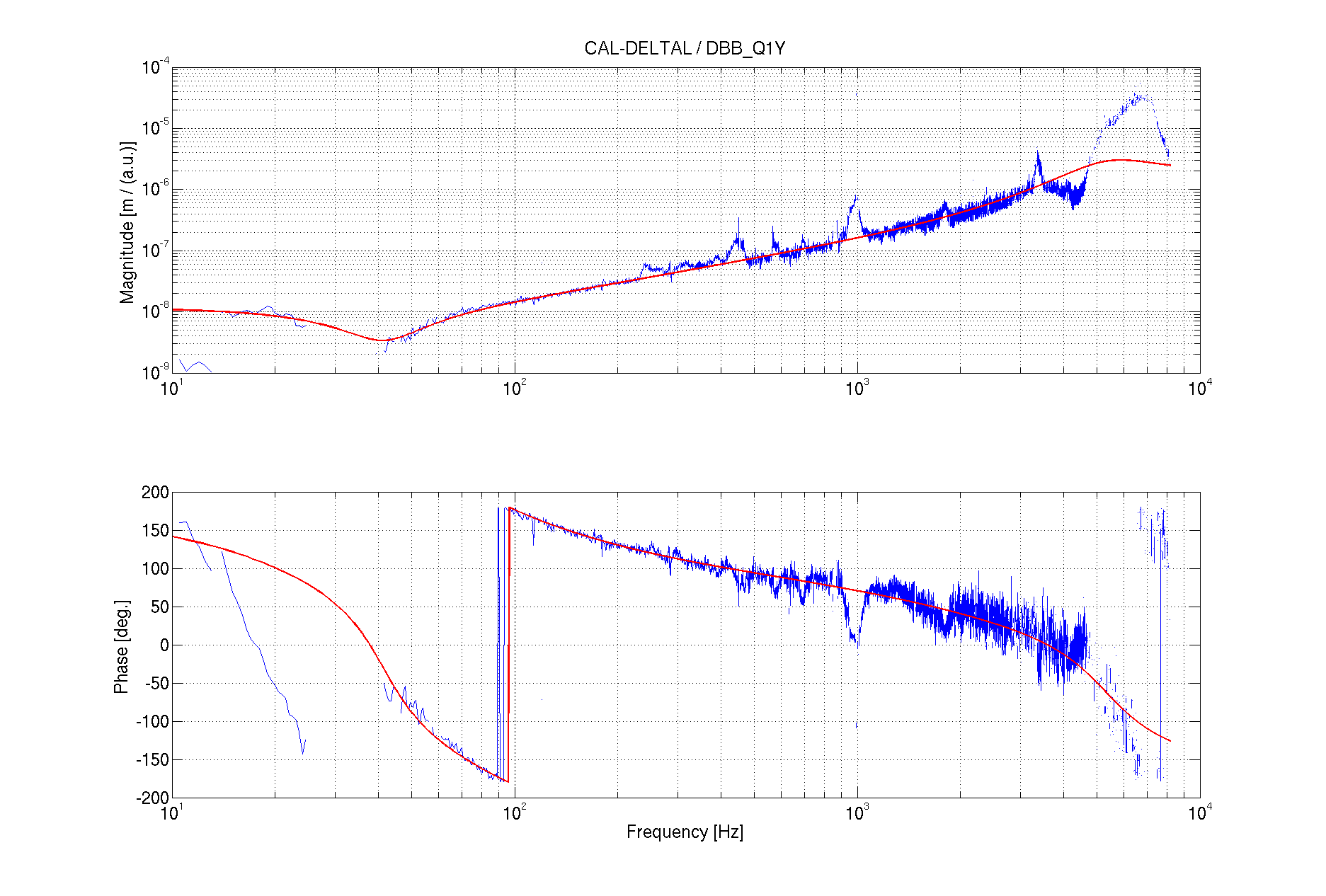
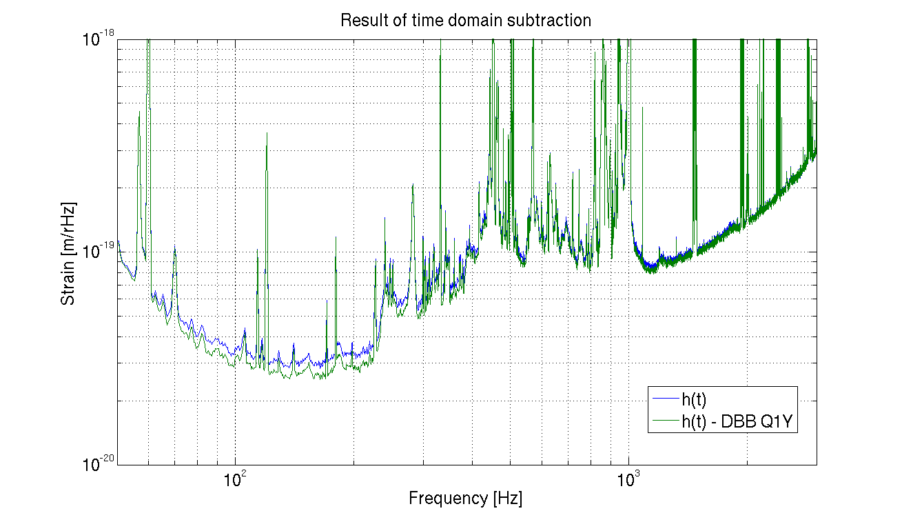
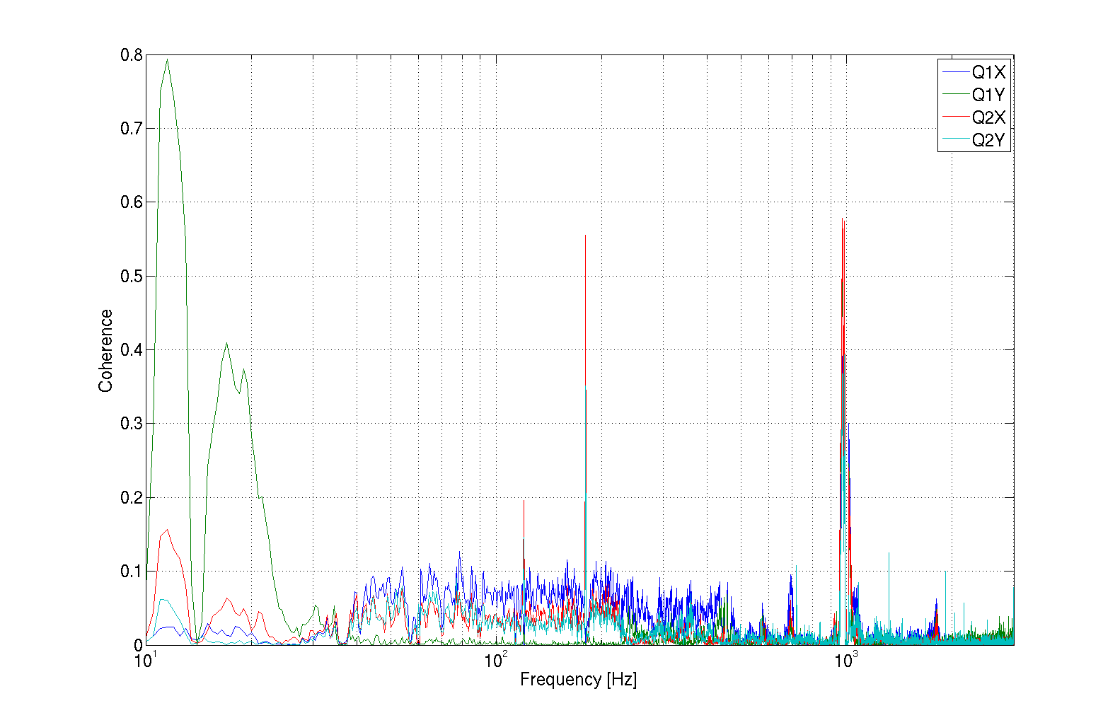
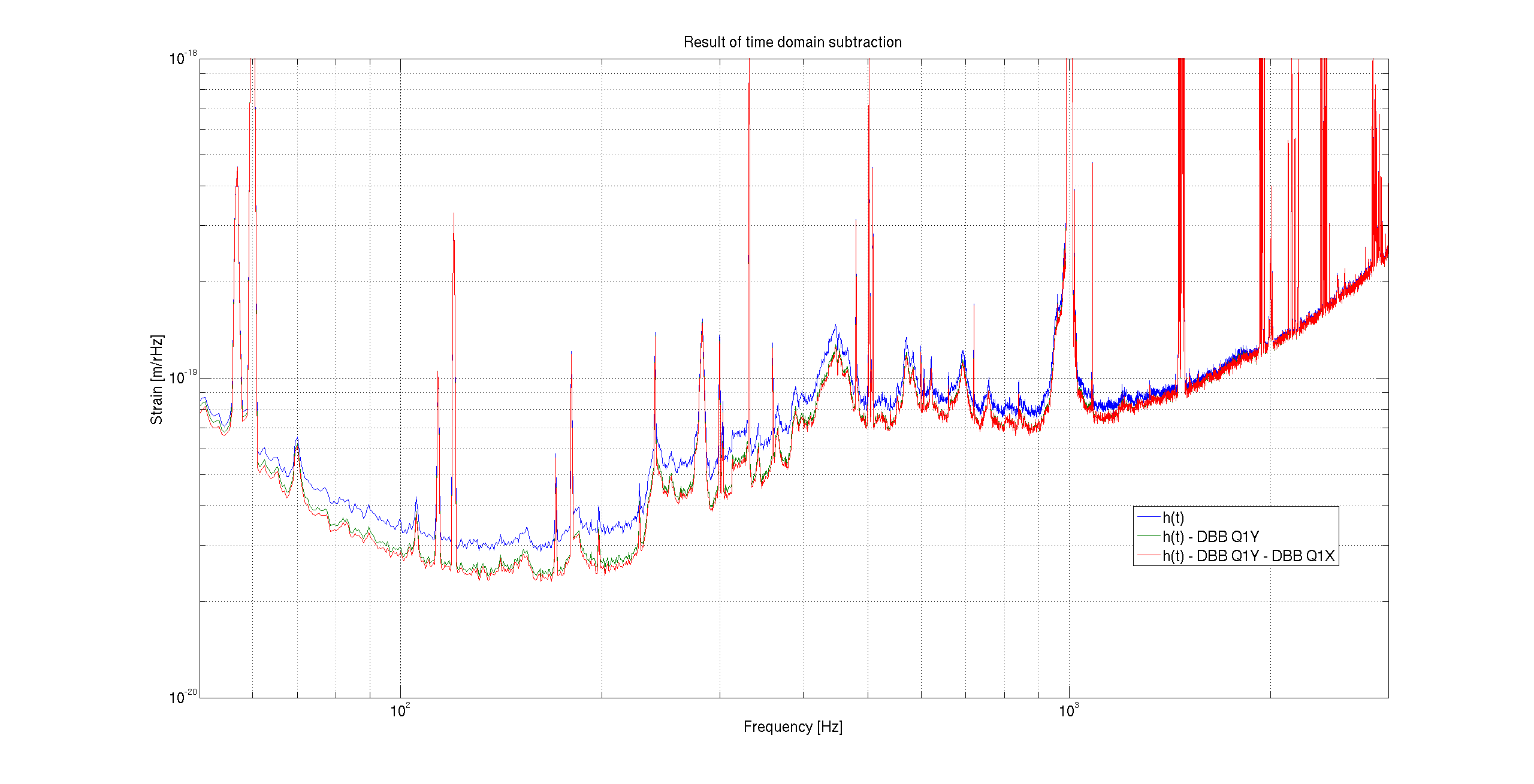
- It looks like the diagnostic breadboard signals are not transfered to the frames in the local cluster, so they are not included in the scan
Additional BruCo scans are available for the PRCL and SRCL error signals:
https://ldas-jobs.ligo.caltech.edu/~gabriele.vajente/bruco_prcl_1159948817/
https://ldas-jobs.ligo.caltech.edu/~gabriele.vajente/bruco_srcl_1159948817/
Images attached to this report
Comments related to this report
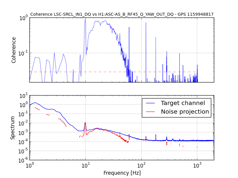
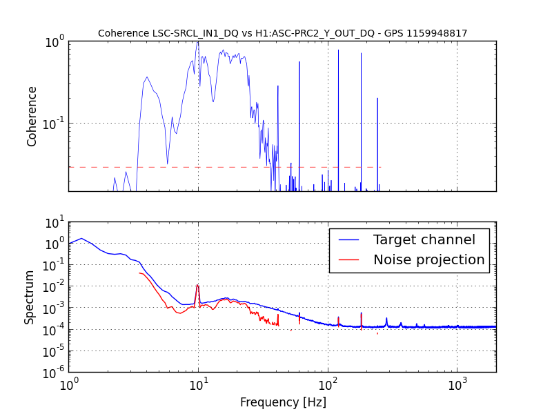
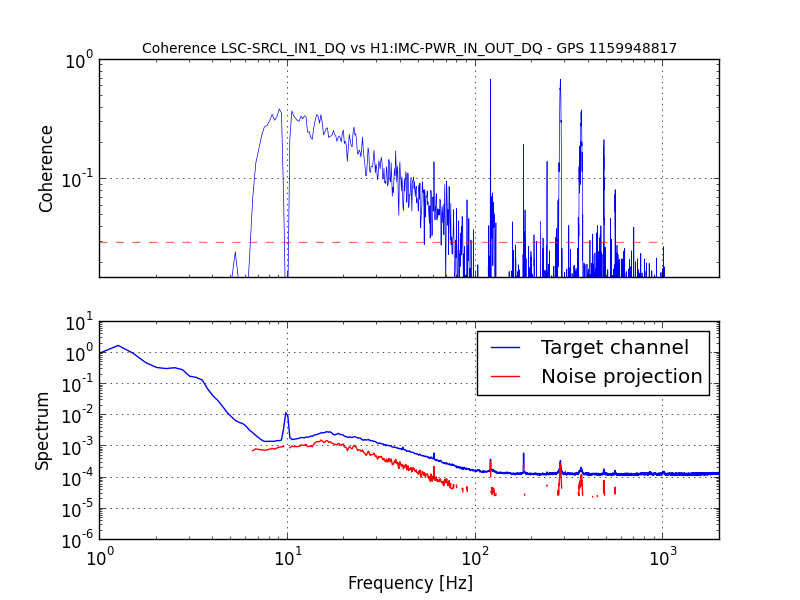
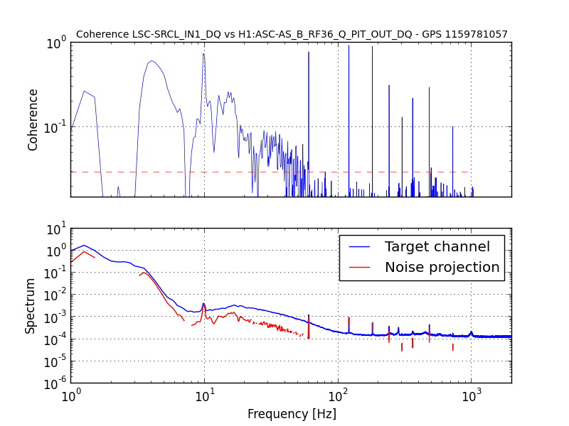
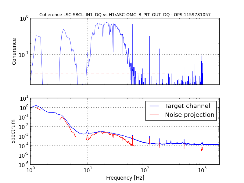
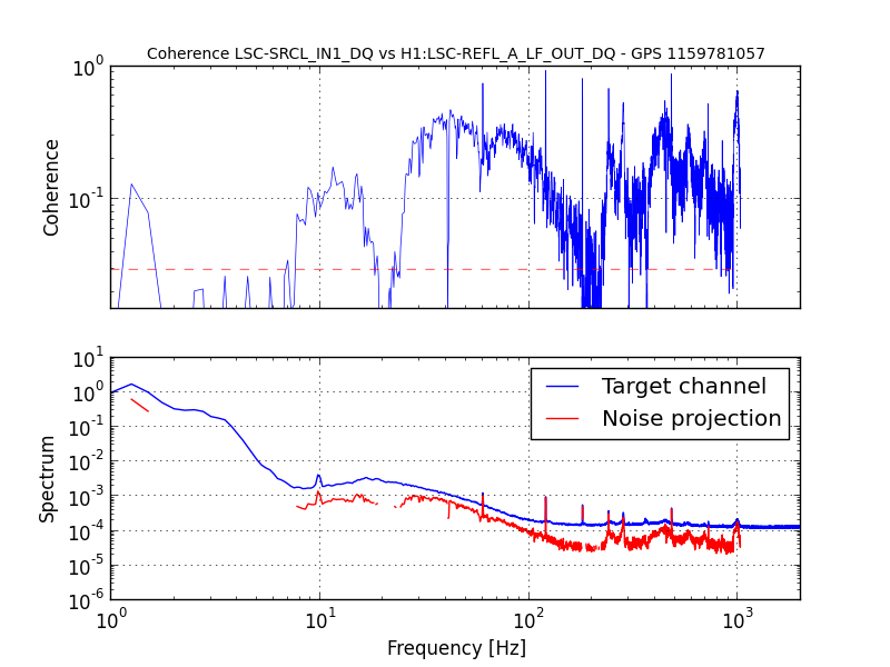
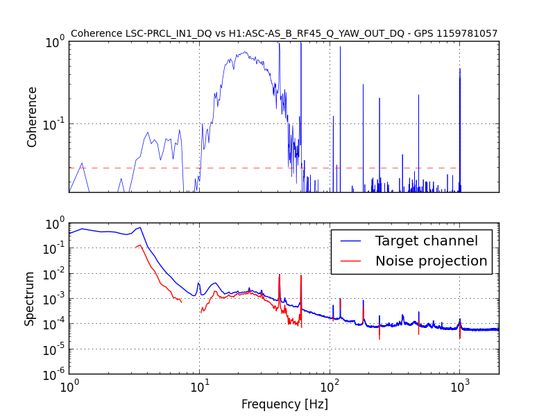
Some interesting coherences with SRCL:
- AS_B_RF45_Q_YAW
- IMC-WFS_A_I_PIT
- ASC-PRC2_Y
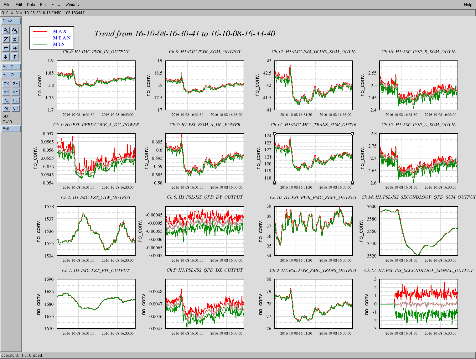
- IMC-PWR_IN
The last one is particularly tantalizing...
Images attached to this comment