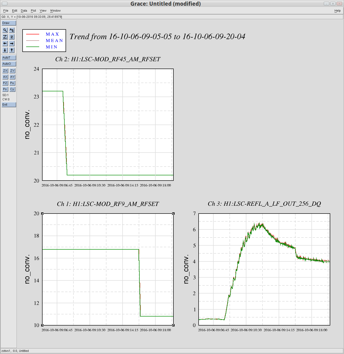
yesterday Jamie, Jim and myself discussed the ramp down issues which were reported by Jenne in alog 30258 Link
here are some notes we made describing the problem.
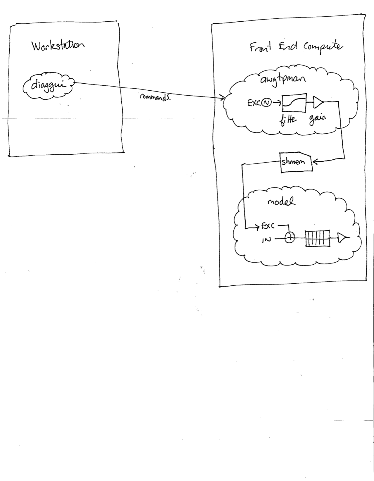
In the figure attached, the diaggui program running on the workstation sends commands over the network to the model's awgtpman process (running on the general core on the front end machine). Inside this process there are three components of the excitation; the excitation itself, an optional user-supplied filter and an output gain stage. The output of the gain stage is sent, via shared memory, the the front end model which writes the excitation signal into the EXC input of the appropriate filter module.
When diaggui completes its measurement or the user presses the abort button, the excitation is ramped down to zero amplitude over the user supplied ramp-time. Normally at this point the output of the gain stage is also zero. The excitation is then stopped, and the EXC input to the filtermodule is zeroed.
In Jenne's case the filter running on the awgtpman rang up even with the excitation writing zero to it. This meant that at the conclusion of the excitation ramp down the output of the gain stage was non-zero, resulting in a sharp step to zero when the excitation was stopped.
Assuming that at the conclusion of the measurement (or if the measurement is aborted) it does not matter whether the excitation ramp-down does or does not go through the filter, then one solution is to ramp the excitation down by ramping the gain to zero. This ensures the output of the gain stage is zero when the exitation is stopped. Jim is reviewing if this is possible and how much programming time this change would take.
We came up with a short term solution in cases where the filter does not zero in the ramp down time. It is possible to run awggui to the excitation test point in order to manually control the gain stage, and diaggui to the same excitation test point to control the excitation. In such case, when the excitation should be stopped the user can ramp the gain down to zero using awggui and then abort the diaggui measurement.
We think this must be set up in advance of the measurement, with awggui started first. The awggui configuration should set the frequency as non-zero (e.g. 1Hz) and the amplitude as zero. When we tried running awggui after diaggui had been started we got errors.