peter.king@LIGO.ORG - posted 13:33, Friday 16 September 2016 (29763)
ISS adjustments
This morning I opened up the ISS photodiode box. The beam incident into the box is attenuated by a polarising beamsplitter
and half waveplate combination. The rejected beam is dumped into an absorbing Schott glass filter. (see ISSBeamDump.jpg)
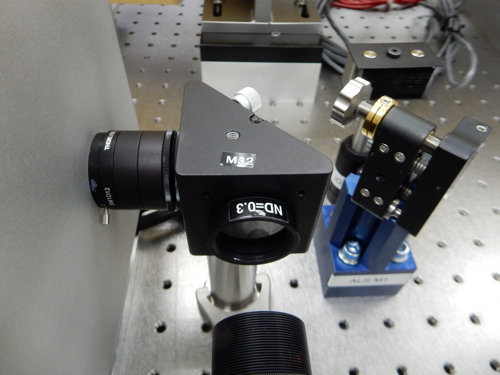
The power going into the photodiode box was measured to be 597 mW. For ease of installation I inserted a neutral density
filter labelled "ND=0.3" at the input to the photodiode box. (see NeutralDensityFilter.jpg). The output of PDA went from
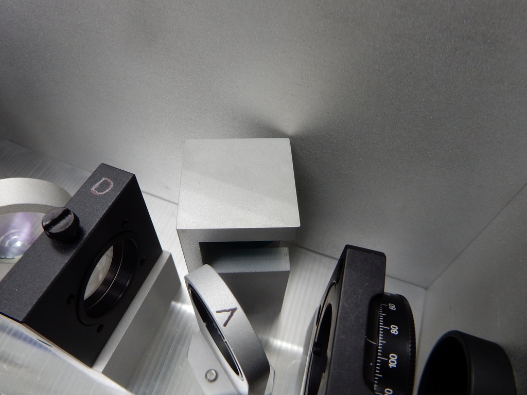
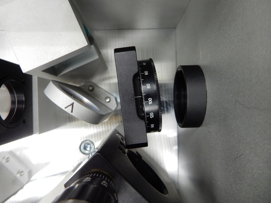
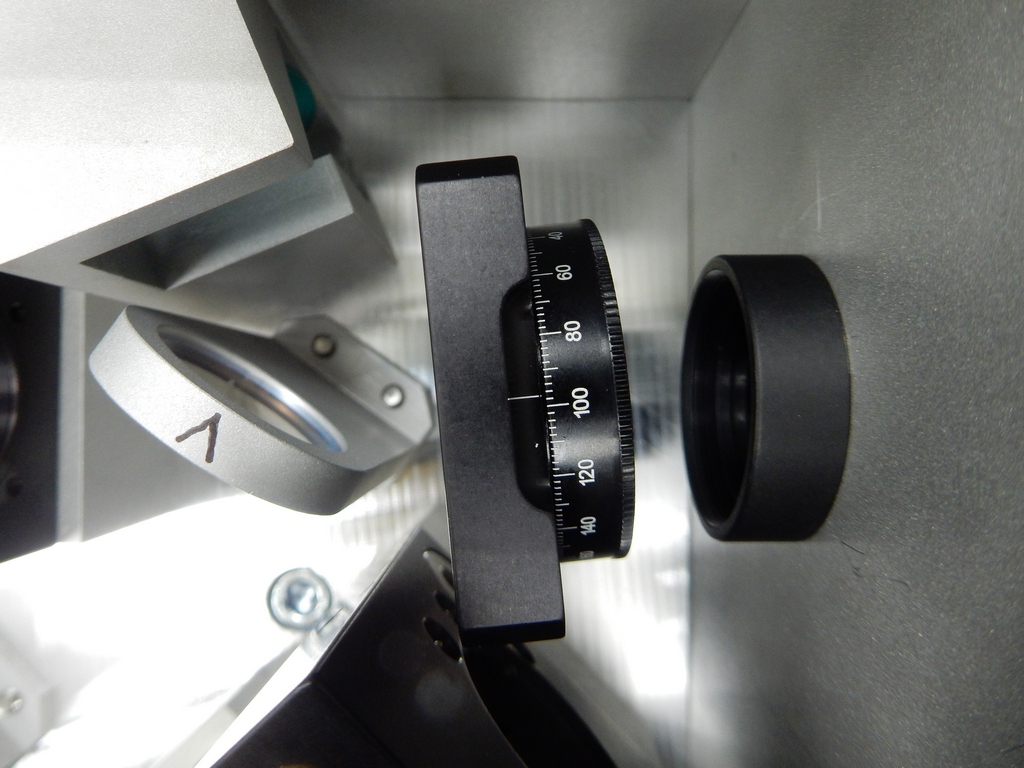
-8.43 +/- 0.07 Vdc to -2.22 +/- 0.01 Vdc, which is somewhat more than one would expect from the label. The half waveplate
was adjusted to bring the output of PDA to -5.22 +/0 -0.03 Vdc (see BeforeWaveplate.jpg and AfterWaveplate.jpg).
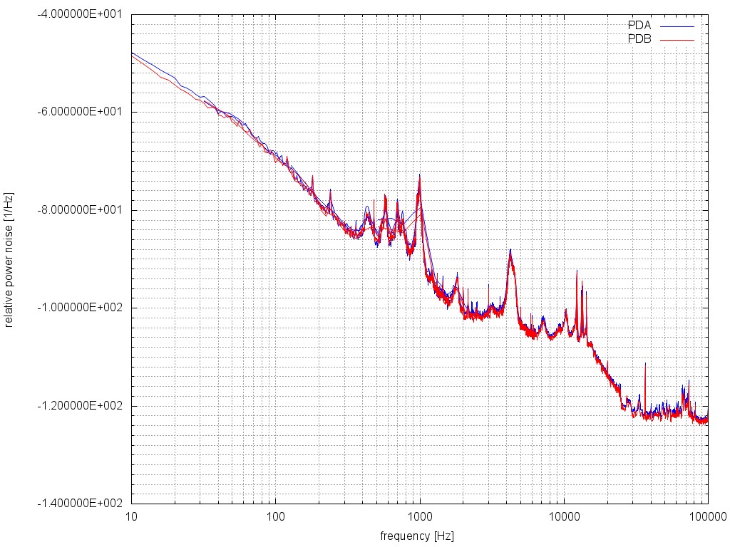
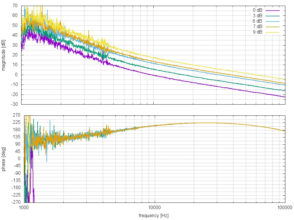
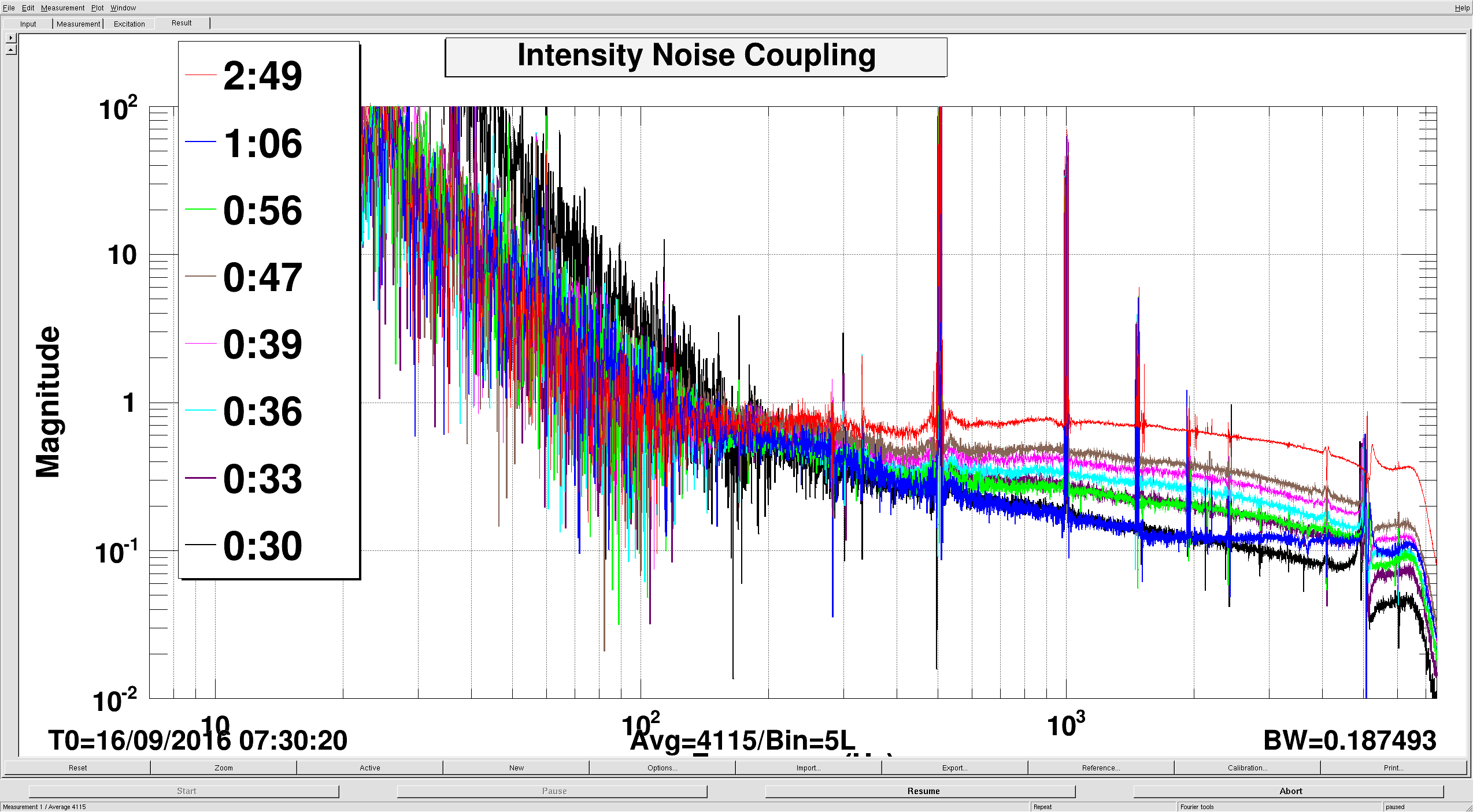
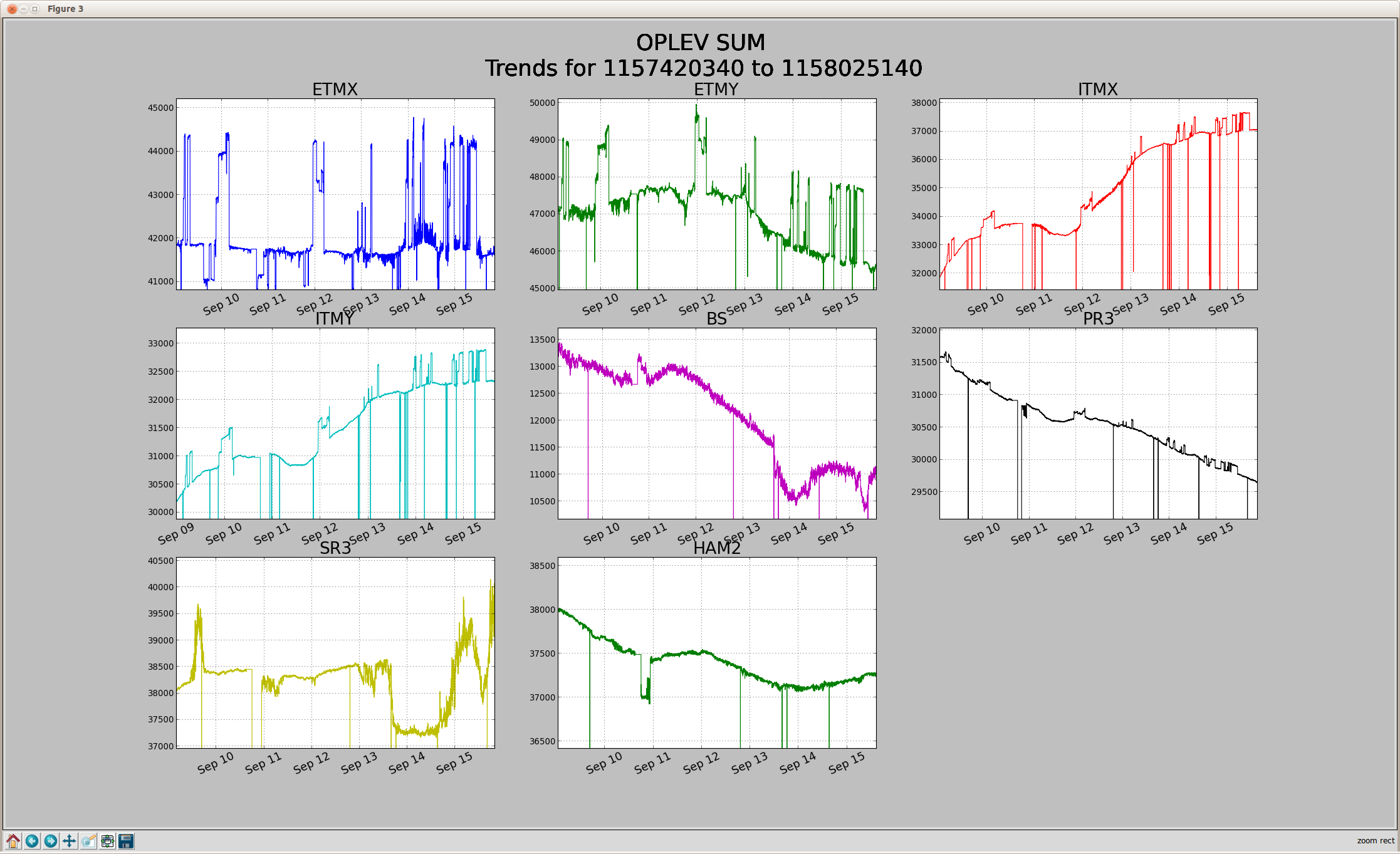
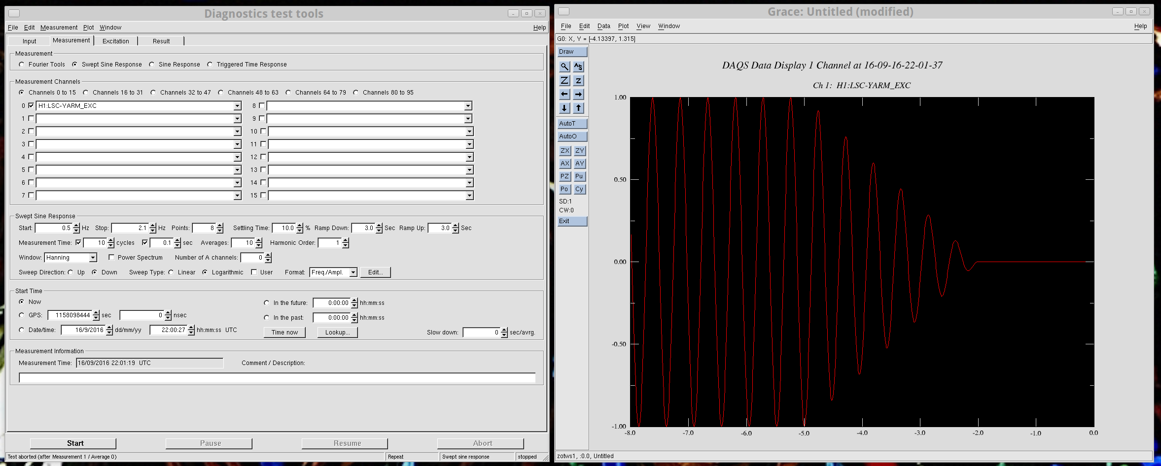
rpn1.jpg shows the free-running spectra as measured by PDA and PDB after the installation of the neutral density filter.
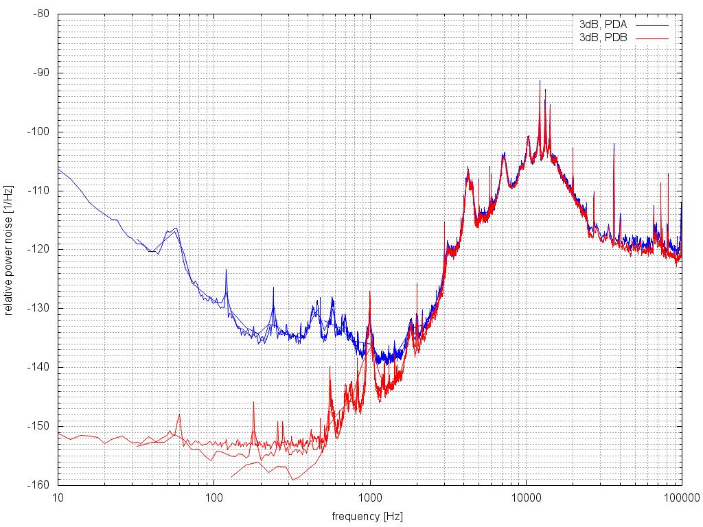
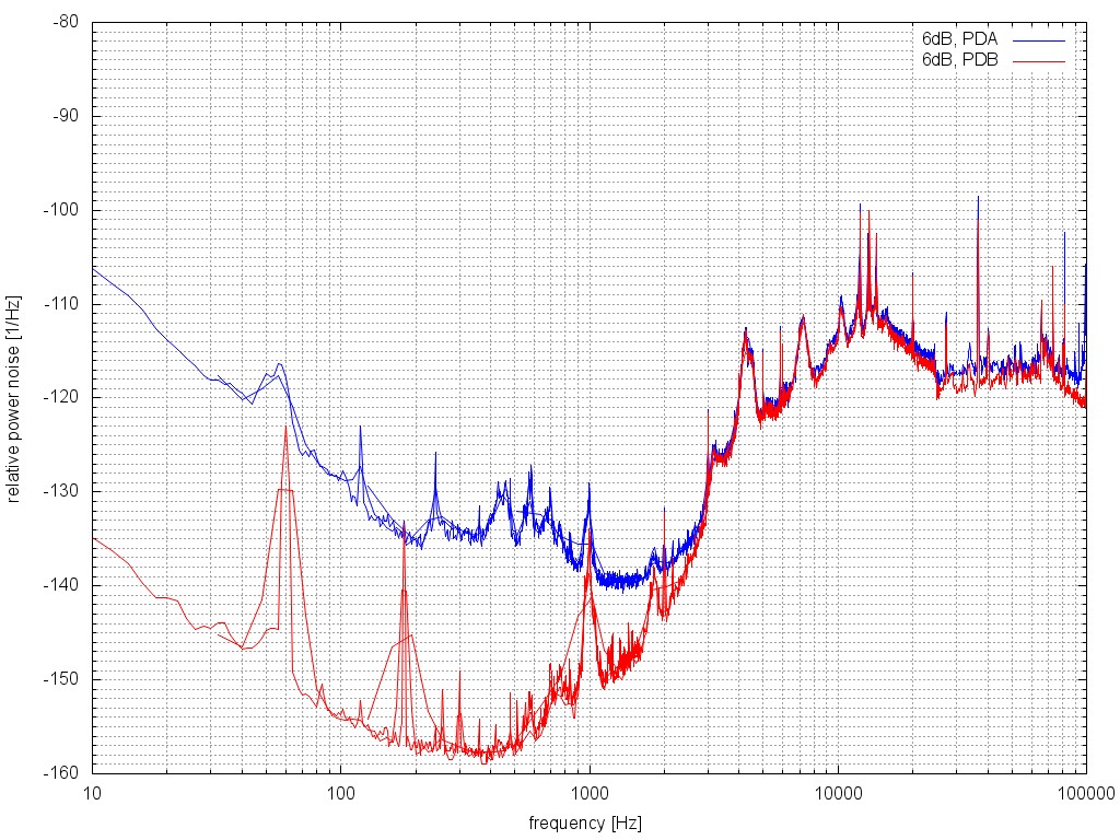
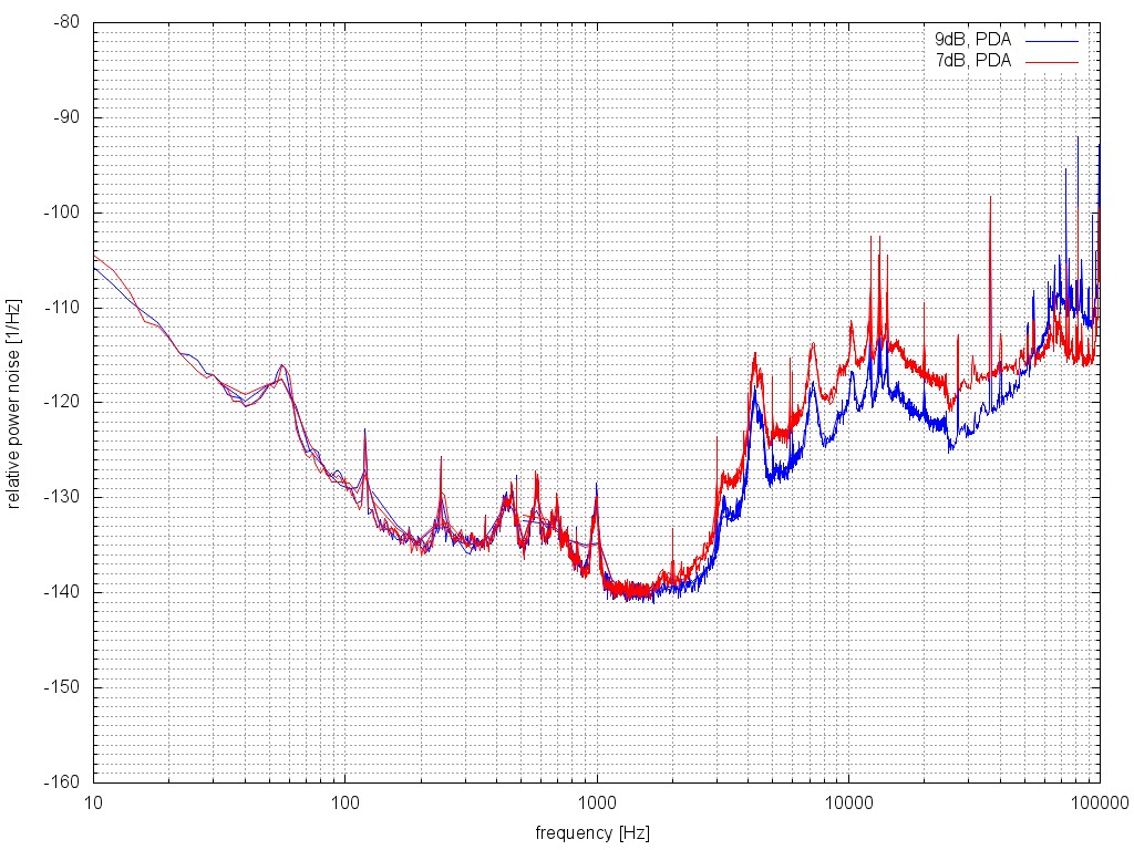
As previously, both agree quite well. Attached are a few other recorded spectra with the differences being the gain slider
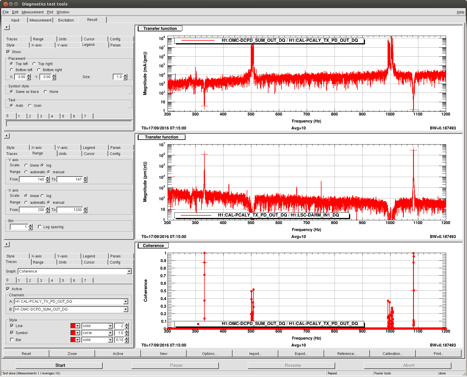
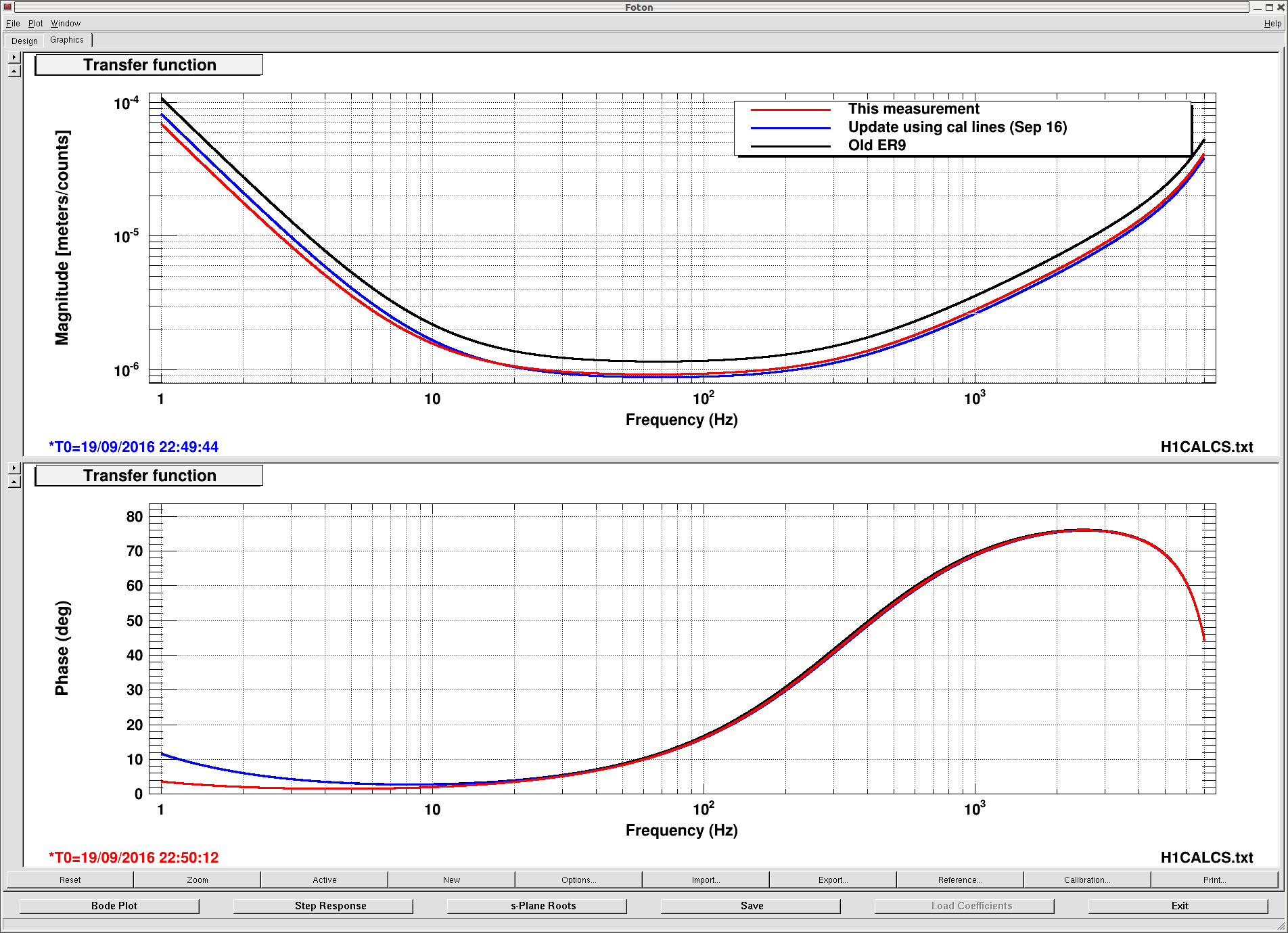
setting. The transfer functions for a few gain slider settings were measured (see ISSTF.jpg).
It is not obvious to me why the in-the-loop noise would increase as the gain increases. See for example g3.jpg and
g6.jpg. So this might be an electronics problem?
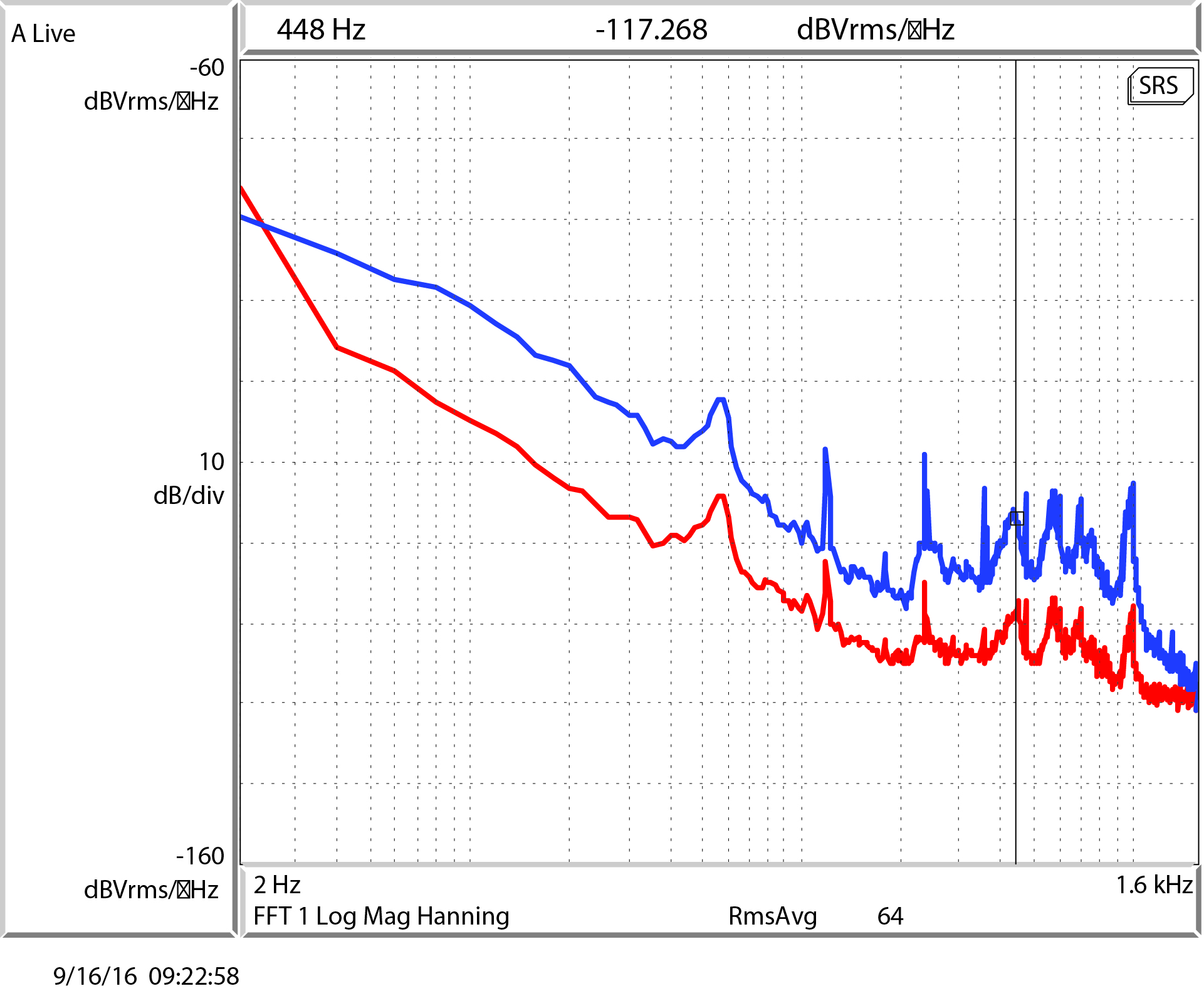
Also attached is the power noise as seen by the PDA55 photodiode that monitors the power going into the input modecleaner.
0.307 mV was the output of the photodiode when the ISS was locked. However it might be that the bandwidth of this photodiode
was only 60 kHz, depending on how the gain selector switch was set. Beyond about 1.6 kHz, the measurement is limited by the
dark noise of the photodiode.
Click here for the datasheet for this obsolete photodiode from Thorlabs
Images attached to this report


