corey.gray@LIGO.ORG - posted 16:05, Thursday 12 May 2016 (27137)
DAY Ops Summary
(All times are local Pacific Standard Time)
Summary:
PSL crew worked in the PSL room in the morning and then H1 was available for locking and commissioning.
SEI Notes:
- SEI group have been working on Guardian, BRS/Sensor Correction stuff, and the ISI Blend medm (on nuc0).
H1 Locking Notes:
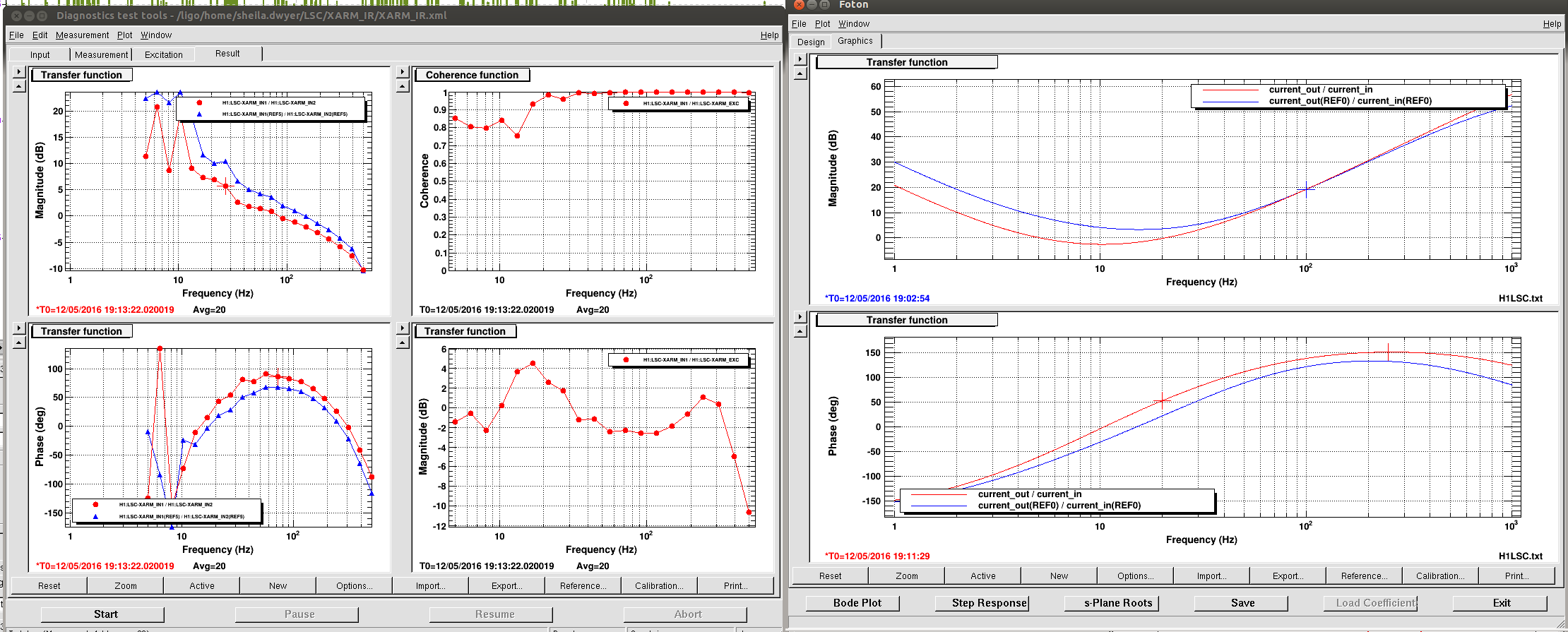
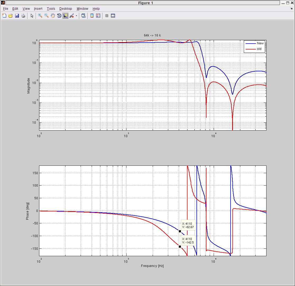
- Attempted locking mid morning and locked DRMI, but it dropped shortly after. Sheila/Jenne later noticed a bad alignment and requested an Initial Alignment; made it to INPUT_ALIGN, and found issues with locking the X-arm in IR (There were people in the H1 PSL room. Sheila also made a filter/gain tweak to the LSC XARM filter bank.)
- After H1 had an Initial Alignment, DRMI and PRMI looked ugly. Traced (Thanks, Sheila!) bad alignment to the PRM's yaw (since misaligning the PRM and tweaking the BS while in PRMI looked fine.)
- At one point, IMC_LOCK Guardian had a FAULT, with TJ's help and also Cheryl's alog, toggled the FSS AUTOLOCKER button off & on. Know you are good when (1) the TPD DC Output is on the order of 3 Volts or more (was getting 0.8V the first few times), AND (2) there are no oscillations on the PZT MON graph on the FSS medm.
- Finally made it to DHARD WFS. Roll Modes looked OK, so we did not engage them. Slowly moved through the ASC Guardian states & eventually made it to DC_READOUT_TRANSITION.
Day's Activities
- 8:11 Dust Monitor Cabling near H1PSL rack (Jeff)
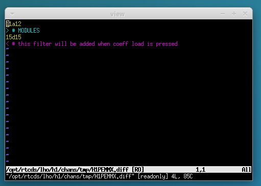
- 8:50-10:00 PEM Cable work (Fil)
- 8:51-9:47 Vertex RGA bake start (Kyle)
- 9:17 LVEA entry for Scroll pump info (Joe D)
- 9:26 Needs to make tape-measure measurement (Chandra)
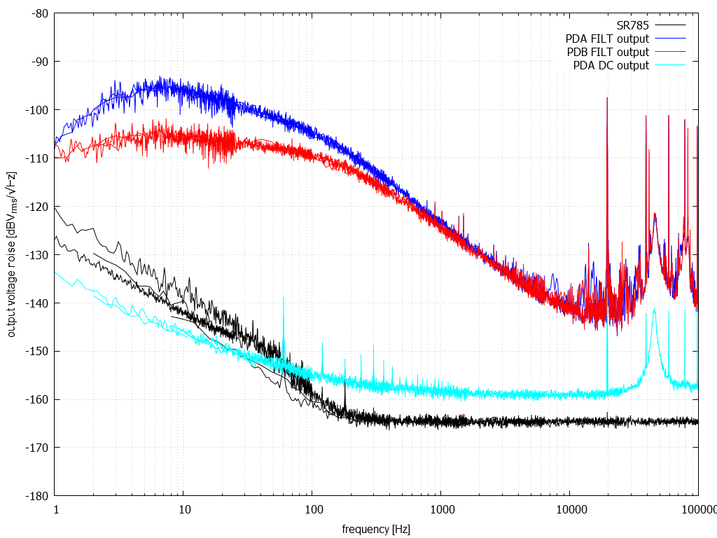
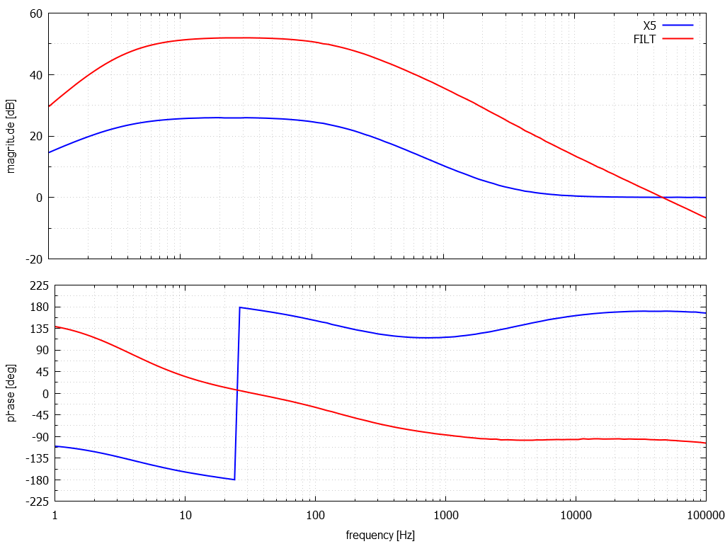
- 9:50 PSL Measurements, working on Diagnostic BreadBoard, for the morning (Peter, Jason)
- 10:30 Checking on TCS Enclosures (Fil)
- 11:33 Checking PSL rack (Keita)
- 1:02 PSL Dust Monitor Alarming begins
- 1:45 Vertex RGA check (Kyle)
- 3:10 Cleaning Area visit (Travis)
- 3:20 Measuring valves at MX (Gerardo)