peter.king@LIGO.ORG - posted 06:48, Wednesday 18 May 2016 (27266)
PSL warrm up
Attached are two files showing the warm up phase of the pre-stabilised laser, after finding the laser was
off due to a chiller fault - as noted in Jeff's entry from last night.
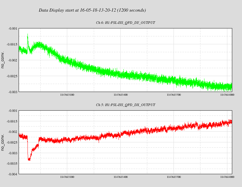
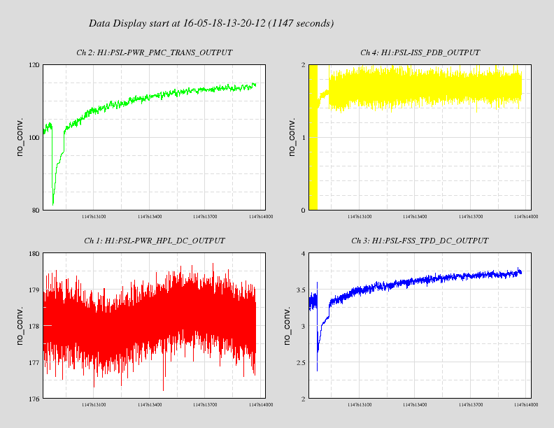
It takes the pre-modecleaner about 10-15 minutes to warm up and come to its final alignment, during
which the transmitted power slowly increases. Other powers follow suit. One can also see that as the
pre-modecleaner settles in, the beam position as monitored by the power stabilisation quadrant photodiode
slowly settles in too.
Images attached to this report