ryan.crouch@LIGO.ORG - posted 16:33, Thursday 07 May 2026 (90153)
OPS Thursday Day shift summary
TITLE: 05/07 Day Shift: 1430-2330 UTC (0730-1630 PST), all times posted in UTC
STATE of H1: Planned Engineering
INCOMING OPERATOR: None
SHIFT SUMMARY: The LVEA is now is laser hazard, HAM2 ISS swap and HAM3 cabling was started today.
LOG:
| Start Time | System | Name | Location | Lazer_Haz | Task | Time End |
|---|---|---|---|---|---|---|
| 13:55 | FAC | Kim | LVEA | N | Tech clean | 14:49 |
| 14:36 | VAC | Jordan | LVEA | N | Check on CP1 and HAM6 RGA | 15:25 |
| 15:37 | FAC | Kim | LVEA | YES | Tech clean | 17:12 |
| 15:50 | FAC | Ibrahim | Optics lab | N | Grab mounts | 16:37 |
| 16:11 | EPO | Mike, Mira | LVEA | N | Tour the LVEA | 16:55 |
| 16:23 | CAL | Tony | PCAL lab | N | Grab equipment | 16:38 |
| 16:24 | SUS | Rahul | LVEA | N | Look for tool pan at HAM2 | 16:29 |
| 16:32 | VAC | Jordan | LVEA | YES | Corner RGA work | 18:35 |
| 16:35 | FAC | Eric | Mezz | N | FAN1 work | 18:15 |
| 16:36 | ISS | Keita, Elenna | Optics Lab / LVEA | n / YES | ISS work | 19:11 |
| 16:38 | SQZ | Sheila | LVEA | N | SQZT7 work | 16:42 |
| 16:42 | SQZ | Tony | LVEA | N | Help Sheila, beam profiler | 19:24 |
| 16:44 | SQZ | Sheila | LVEA | YES | LazHaz transition then beam profiling | 19:24 |
| 16:59 | ISS | Rahul, Jennie | Opt Lab / LVEA | n / YES | ISS work | 19:09 |
| 17:02 | SQZ | Ryan S | LVEA | YES | Beam profiling | 19:24 |
| 17:17 | FAC | Kim | EX | n | Tech clean | 18:02 |
| 18:02 | FAC | Kim | EY | n | Tech clean | 19:23 |
| 18:18 | ContCont | Robert | LVEA | YES | BSC2 contamination control | 20:37 |
| 18:32 | EPO | Anna + film crew | LVEA | YES | Filming | 20:07 |
| 18:35 | ISS | Jenne | LVEA | YES | Locking JAC | 19:06 |
| 19:09 | EPO | Ibrahim | LVEA | YES | LVEA tour | 19:49 |
| 19:43 | SAF | LVEA IS LASER HAZARD | LVEA | Y | LVEA IS LASER HAZARD | 04:03 |
| 19:49 | SEI | Jim | EndY | N | Check out BRS-Y heater and wind fence | 21:01 |
| 20:34 | SUS | Betsy, Ibrahim | LVEA | Y | BBS cleaning cont. done at 22:25 | 22:56 |
| 20:38 | VAC | Jordan, Anna + film crew | LVEA | Y | X1 beamtube enclosure | 21:13 |
| 20:46 | ISC | Rahul, Elenna, Madi, Disha, Keita | LVEA | Y | ISS work HAM2, Disha Madi out @ 21:41, everyone except Keita 22:56 | 23:33 |
| 20:51 | EE | Fil | LVEA | Y | Cables by HAM3 | 22:17 |
| 20:53 | SAF | Richard | LVEA | Y | Check work by HAM2 | 21:04 |
| 21:12 | SQZ | Sheila, RyanS, Tony | LVEA | Y | SQZT7 beam profiling, Tony Ryan out at 22:30 | 22:55 |
| 21:13 | VAC | Jordan | LVEA | Y | RGA work by HAM6 | 22:45 |
| 21:22 | ISC | Jenne | LVEA | Y | Join/assist HAM2 crew | 21:49 |
| 21:31 | ISC | Jennie | LVEA | Y | HAM3 work | 22:30 |
| 22:25 | ISC | Jenne | LVEA | Y | HAM3 work | 23:30 |
| 22:43 | SUS | Betsy, Ibrahim | LVEA | Y | ITM cover | 23:43 |
| 22:51 | OPS | Corey | CER | Y | Grab a vacuum | 22:56 |
| 23:30 | IAS | Jason | LVEA | Y | FARO auto power off/on | 22:45 |


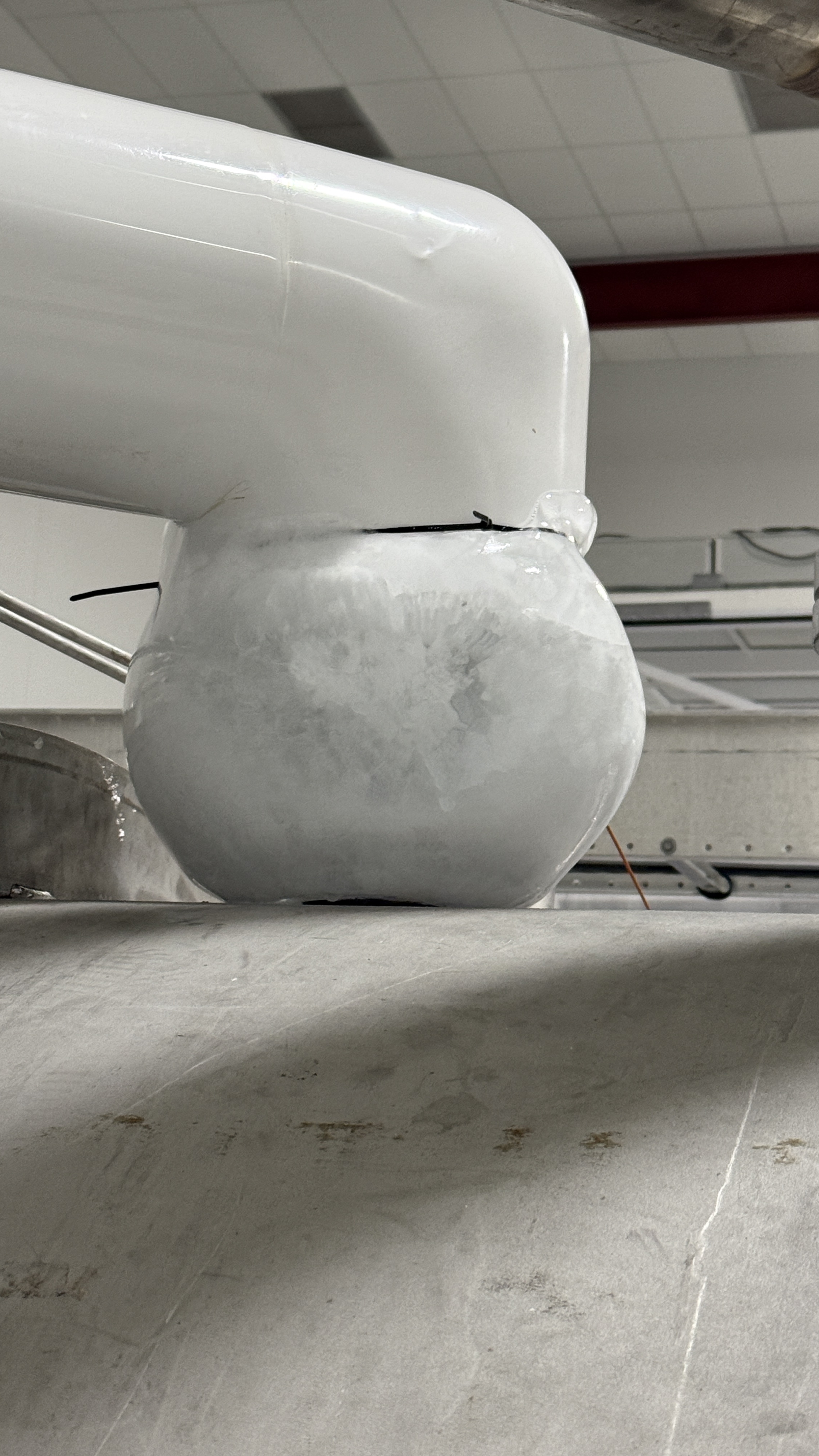


About the installed unit.
New ISS unit is SN1202965 with a base D1101073 (ALIGO IO PSL ISS PD L1 BASE).
Our plan was/is to reuse the base that is already in chamber, D1101074 (ALIGO IO PSL ISS PD H1 BASE), together with the strain relief assemby. (FYI, there's also supposed to be an obsolete base D1101075, ALIGO IO PSL ISS PD H2 BASE.) In other words, in the first attachment, the parts outlined in red will stay in chamber, only the blue part will be replaced.
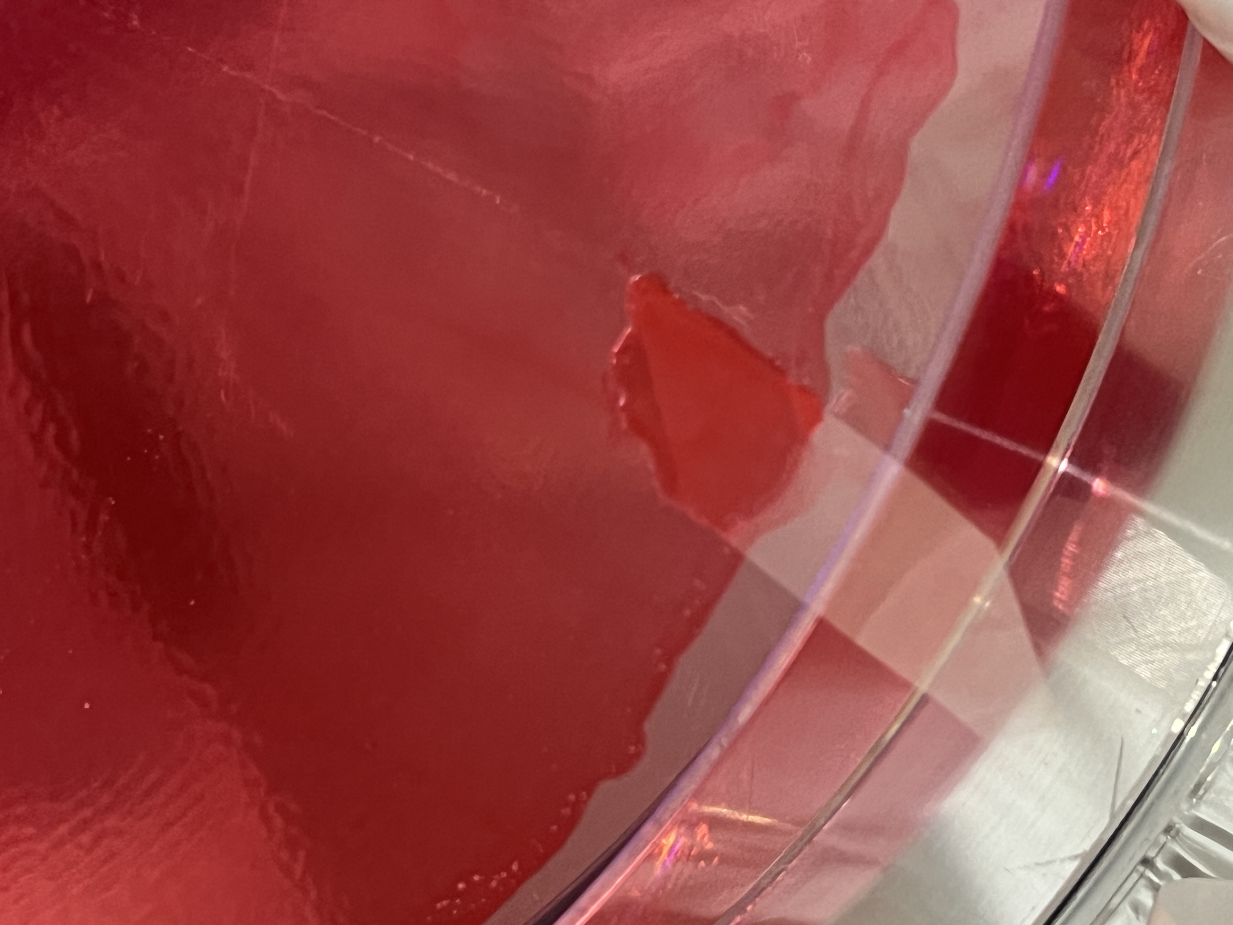
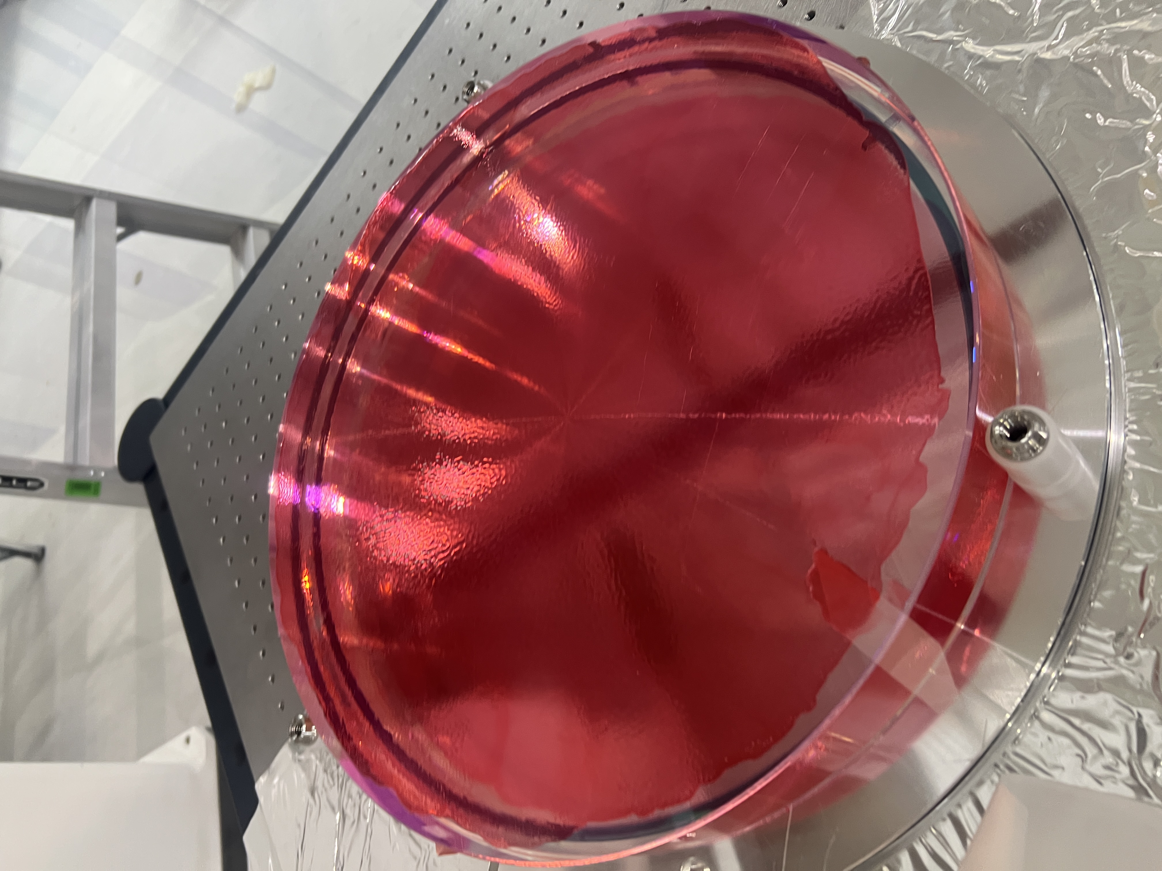
One complication is to make sure that the SMP cables are connected to the PDs in correct polarity, otherwise the PDs will be forward-biased and damaged. However, it turns out that array PDs in the new one we're installing and the old one in chamber are all angled in a consistent manner that, seen from the back of the PDs, cathode is to the left and anode is to the right. See the 2nd (new unit) and the 3rd/4th picture (old one). This means that we don't have to use tags or anything to ID SMP cables, all we need to do is to make sure that the cables won't fall out of the strain relief. Once the main body of the array (PD array and QPD) is swapped, we can just connect cables based on the position of the strain relief holes they're in.
A note about misalignment of the IMC seen from inside HAM2.
We did not see "flashes" because it didn't flash at all. We were able to see the MC1 transmission and the return beam after one round trip inside the IMC, and the latter was more than 1" higher than the former. There was also YAW difference. All in all two beams were about 1.5" apart. MC1 transmission beam position looked OK.
This was eventually traced back to the problem of MC2 top OSEMs, which will be alog-ed by somebody else.
tagging for photos