Matt, Daniel, Patrick, Vern, Kiwamu,
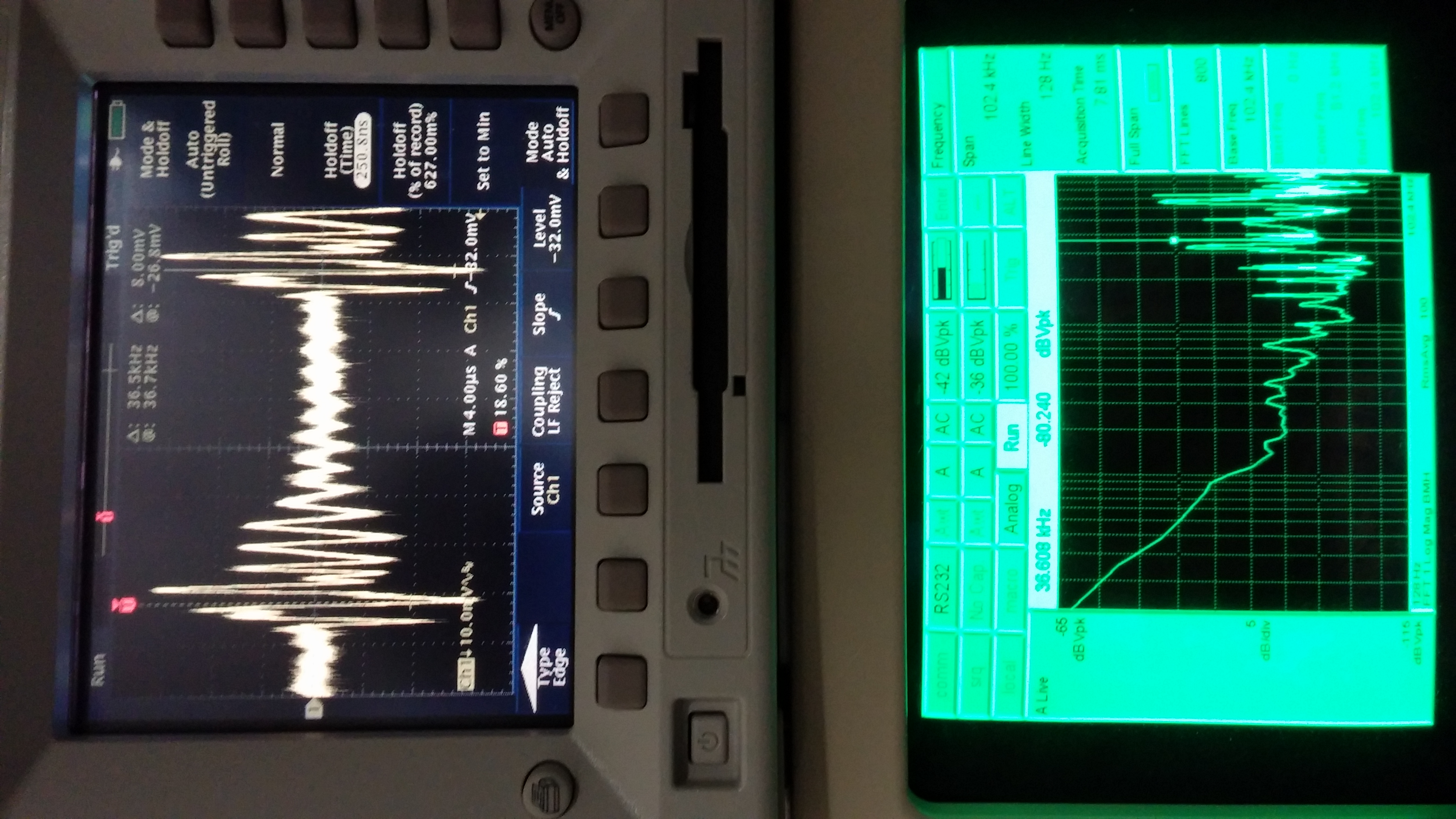
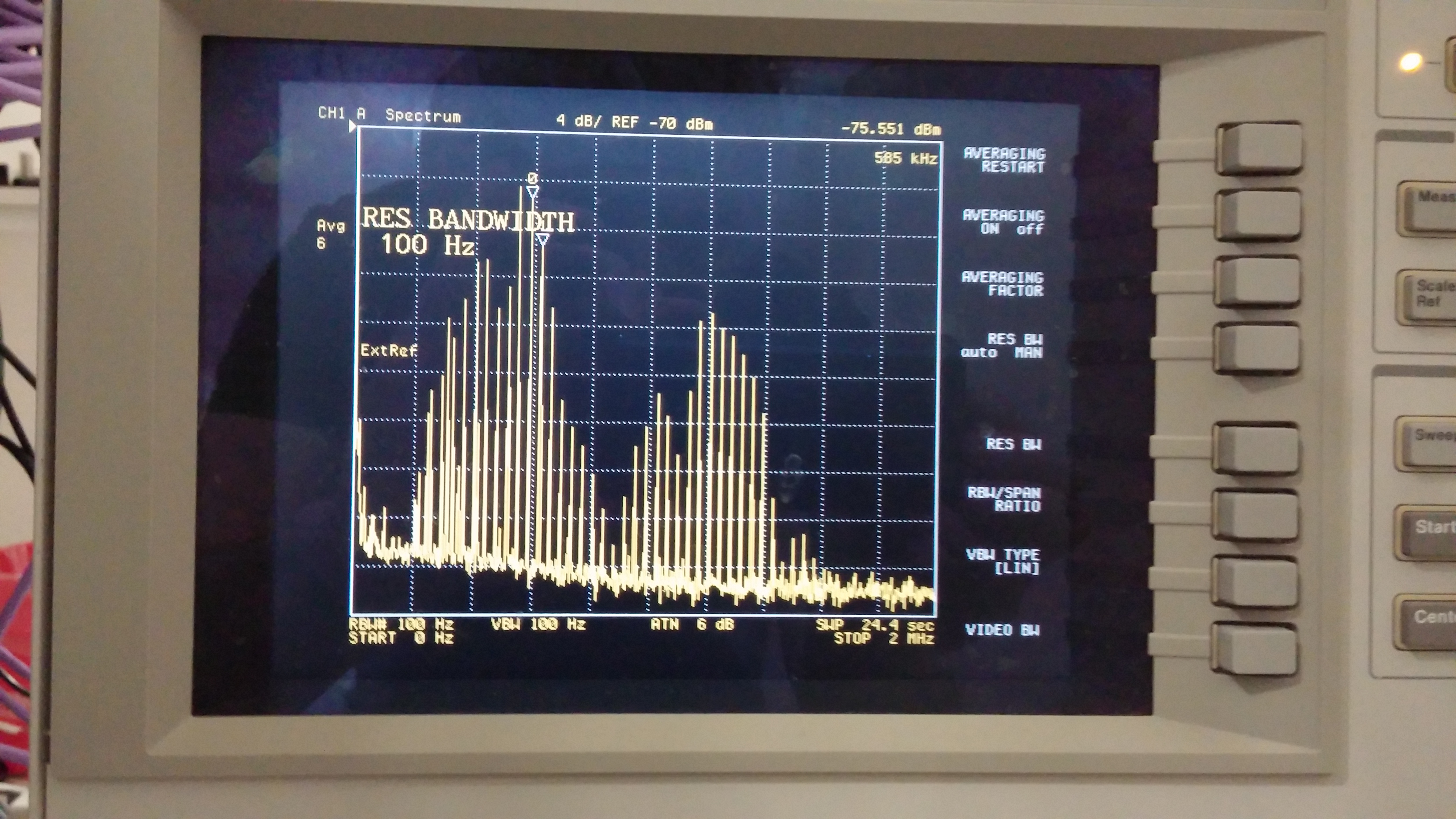
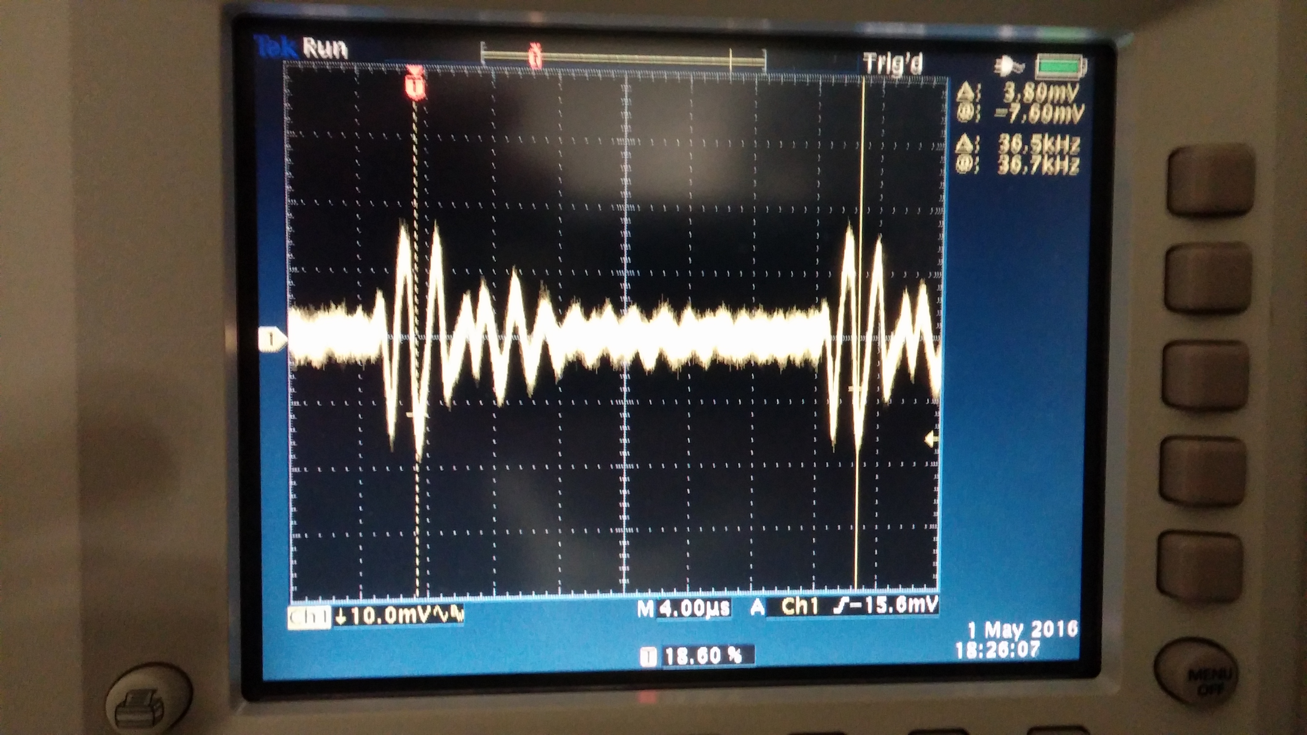
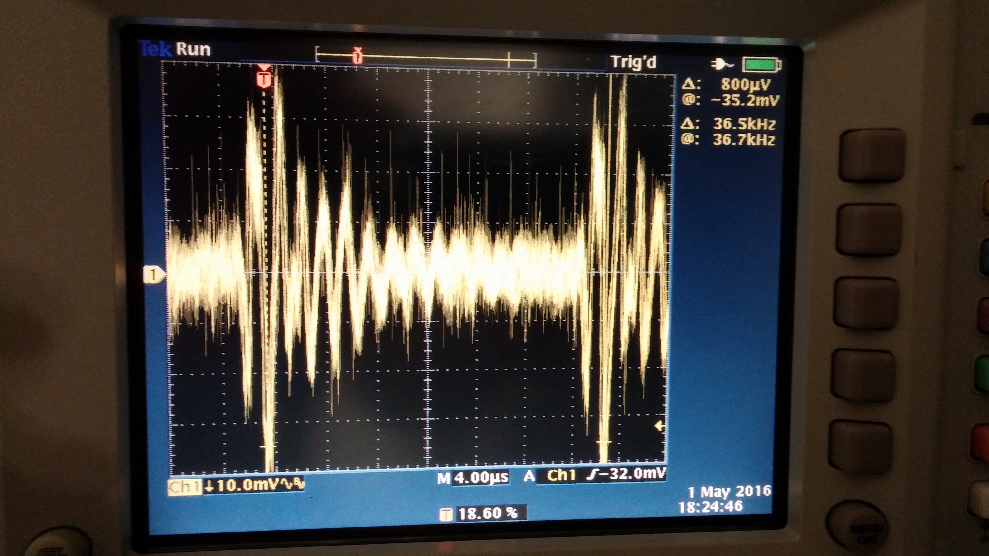
We have spent a day trying to improve the behavior of the PSL rotation stage. Its performance is much better now (the angle accuracy is about several mdeg). We identified two major issues as follows which are now fixed.
-
The glitch issue (rotation stage goes backward at the beginnig of a rotation action for a short period)
-
The accuracy issue (accuracy of the terminal angle is only as good as 0.1 deg)
In contrast, we started having a (new) minor issue where occasionally the rotation stage does not exit the busy mode on its own. If this happens a user should manually hit the abort button to terminate the busy state.
[Some details]
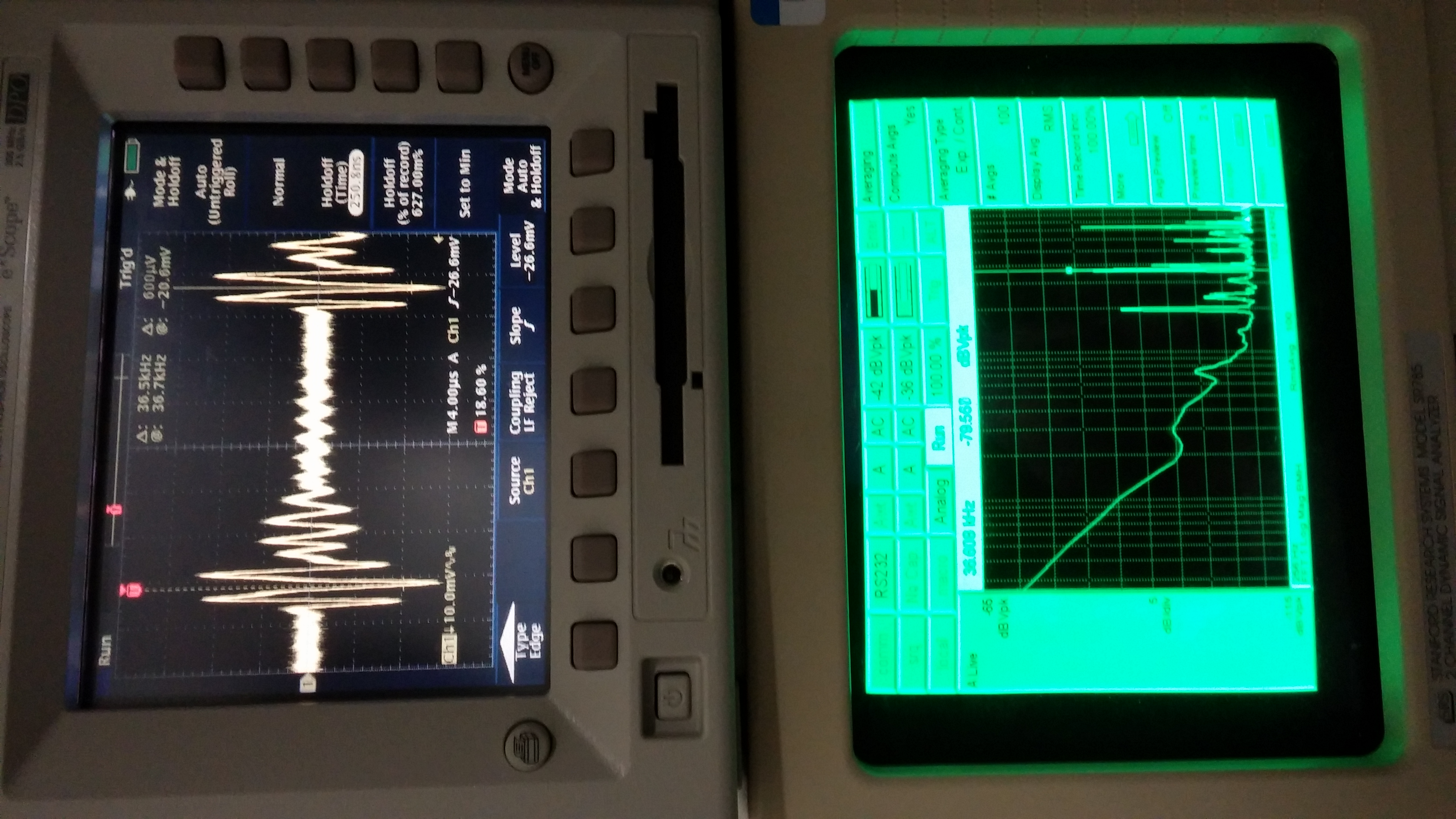
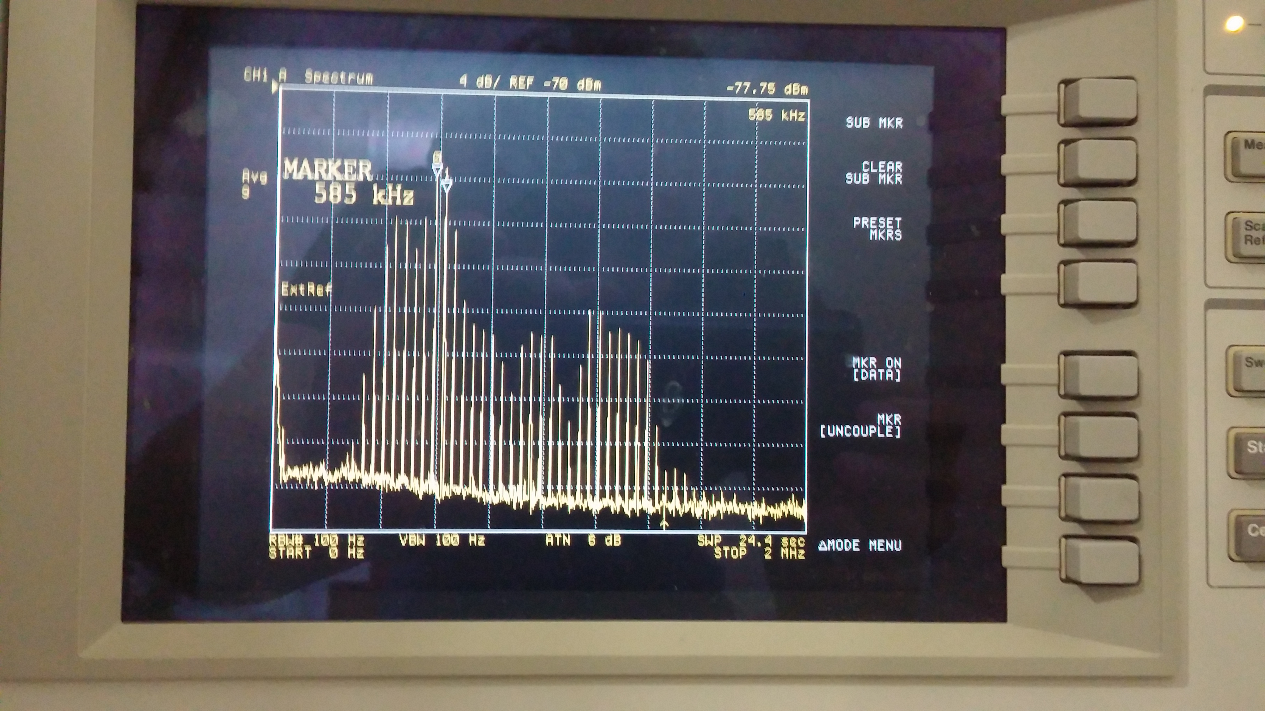
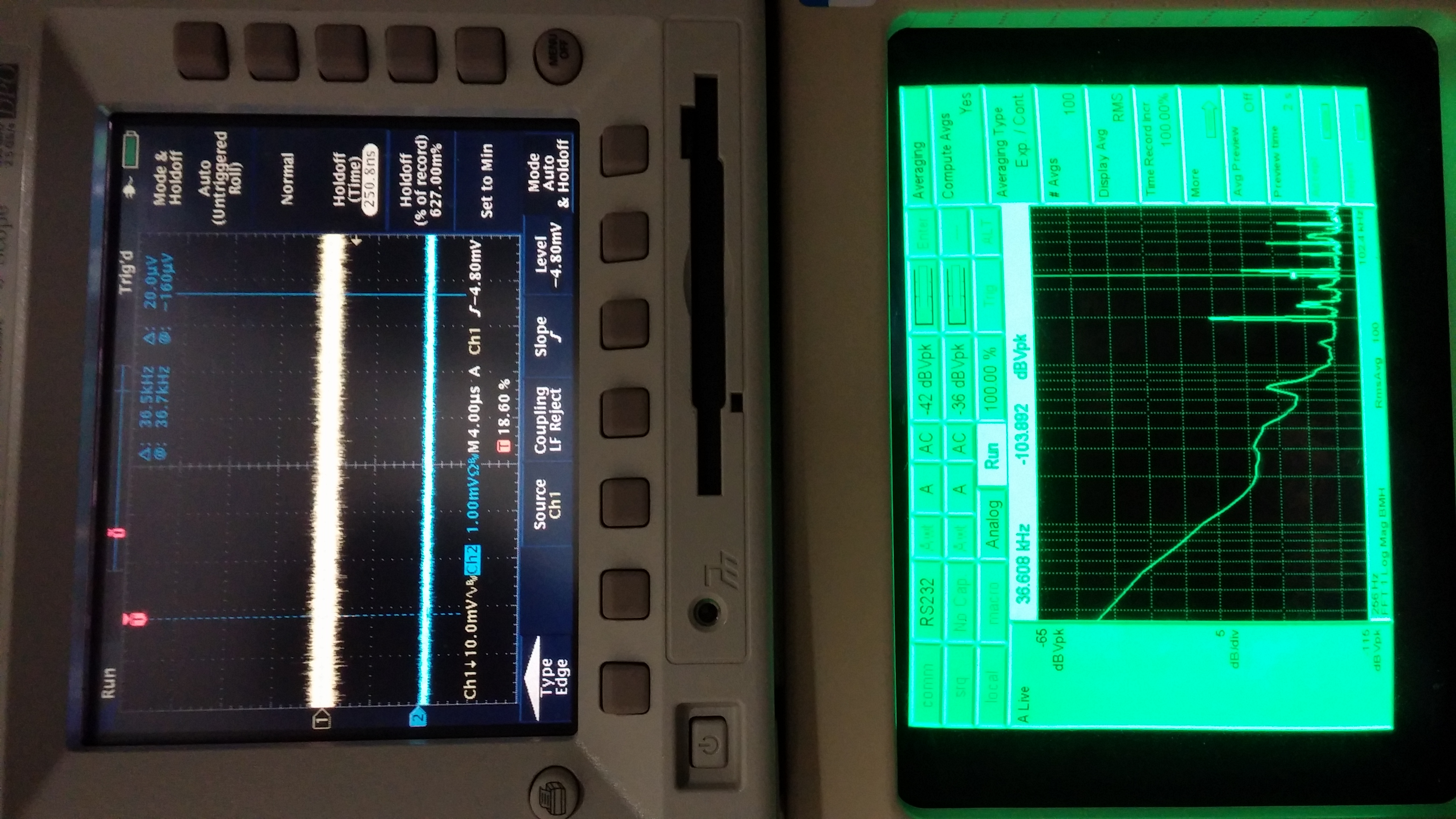
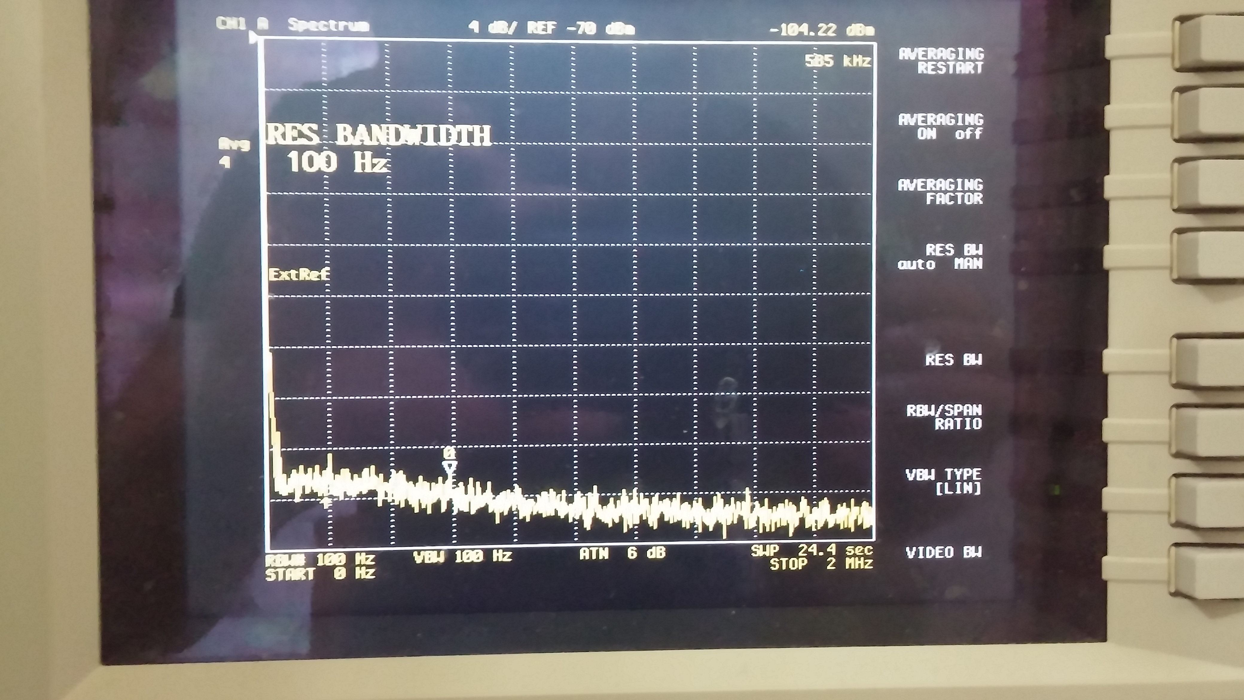
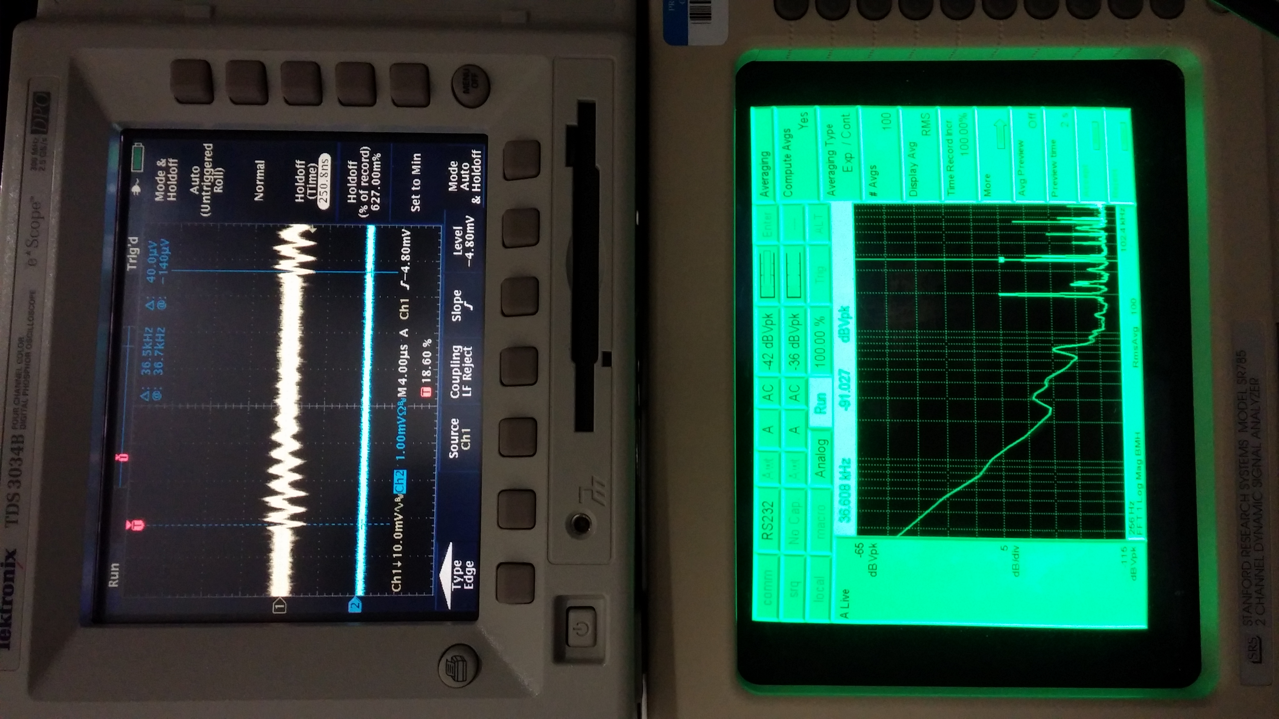
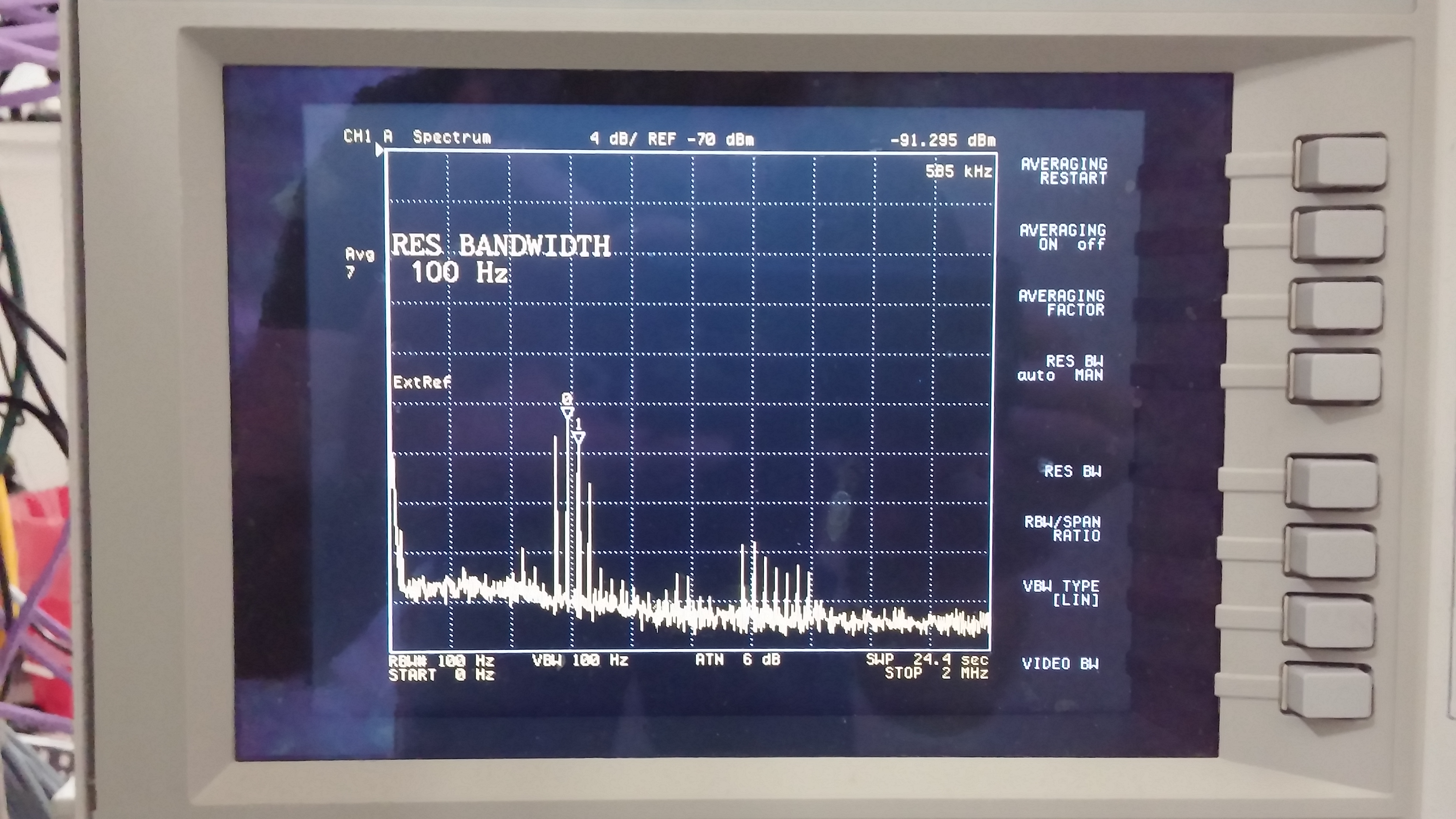
First of all, we discovered that the size of the glitch scaled with the size of the error (or the residual) that the previous rotation action has left. This lead us to the conclusion that the accuracy of the rotation stage was not good enough and the PID parameter needed some tuning. In addition, we discovered that the maximum motor velocity was set to a too high value. We were using only a very small fraction of the maximum velocity (0.1 % of the maximum nominally). Ideally, this should not impact on the performance at all, but we guessed that this caused some nasty numerical rounding error or something similar when calculating the output integer value for driving the stage. Indeed, decreasing the maximum motor velocity from 3600 to 100 drastically improved the terminal angle precision by more than a factor of 10. So the terminal angle is now as accurate as ~mdeg with a repeatable bias of 70 counts or so.
Also, we noticed that the acceleration and deceleration times were set with respect to the maximum velocity, rather than to the requested velocity. As we decreased the motor maximum velocity, the acceleration and deceleration became more apparent. (Did we change some other parameters relating to the acceleration and deceleration ?)
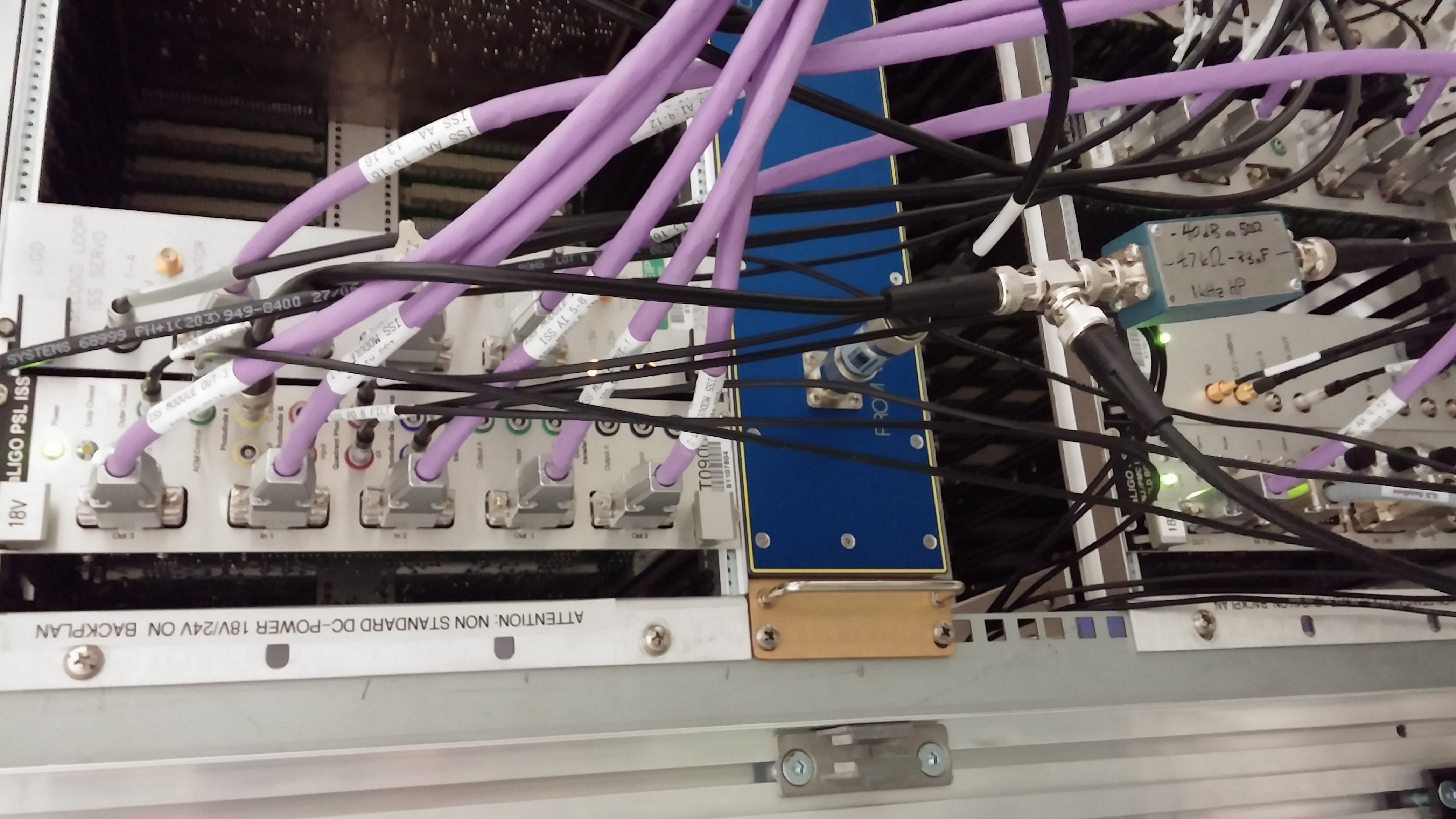
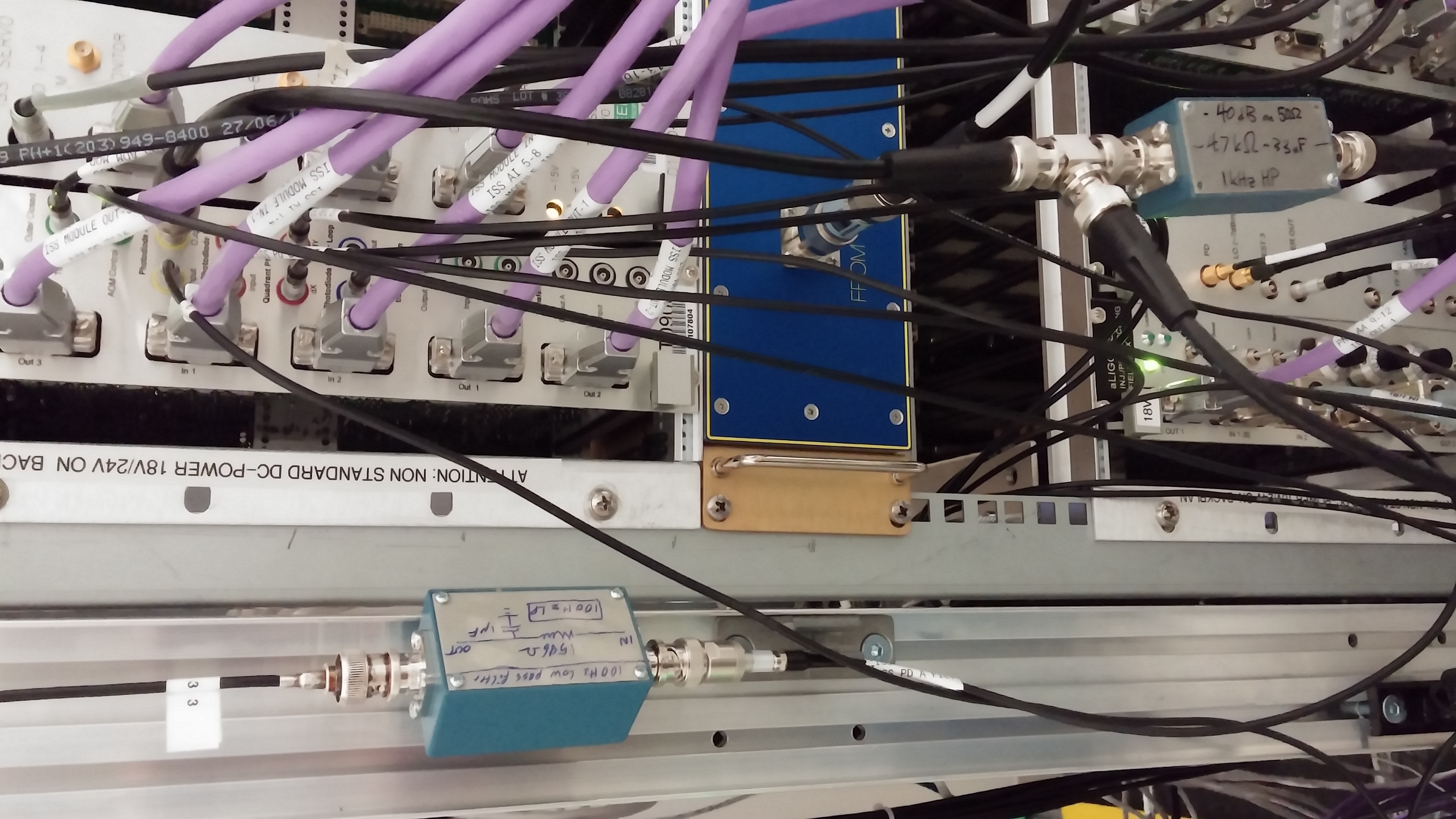
In order to further improve the accuracy, Daniel and Vern installed an additional load resistor of 50 Ohm in the path that drives the motor. Because we made multiple changes at the same time, unfortunately it was unclear how much this improved the resulting angle accuracy. Nevertheless, according to the drive monitor, it is now able to stably and continuously drive the motor without stopping multiple times during a rotation action. So we think this additional load helped the overall performance somewhat.
We then tuned up the PID parameter again. After all, the P-factor (aka Kp) happened to be back to the default value of 200. The I-value (aka Ki) is currently 20, while the default value was 2. However, we found that Ki did not really change the behavior, this value seems fine for now.


