jeffrey.kissel@LIGO.ORG - posted 16:09, Friday 26 February 2016 (25759)
Charge Measurement Update; Feb 16th Bias flips Successful, Charge on its way back to zero
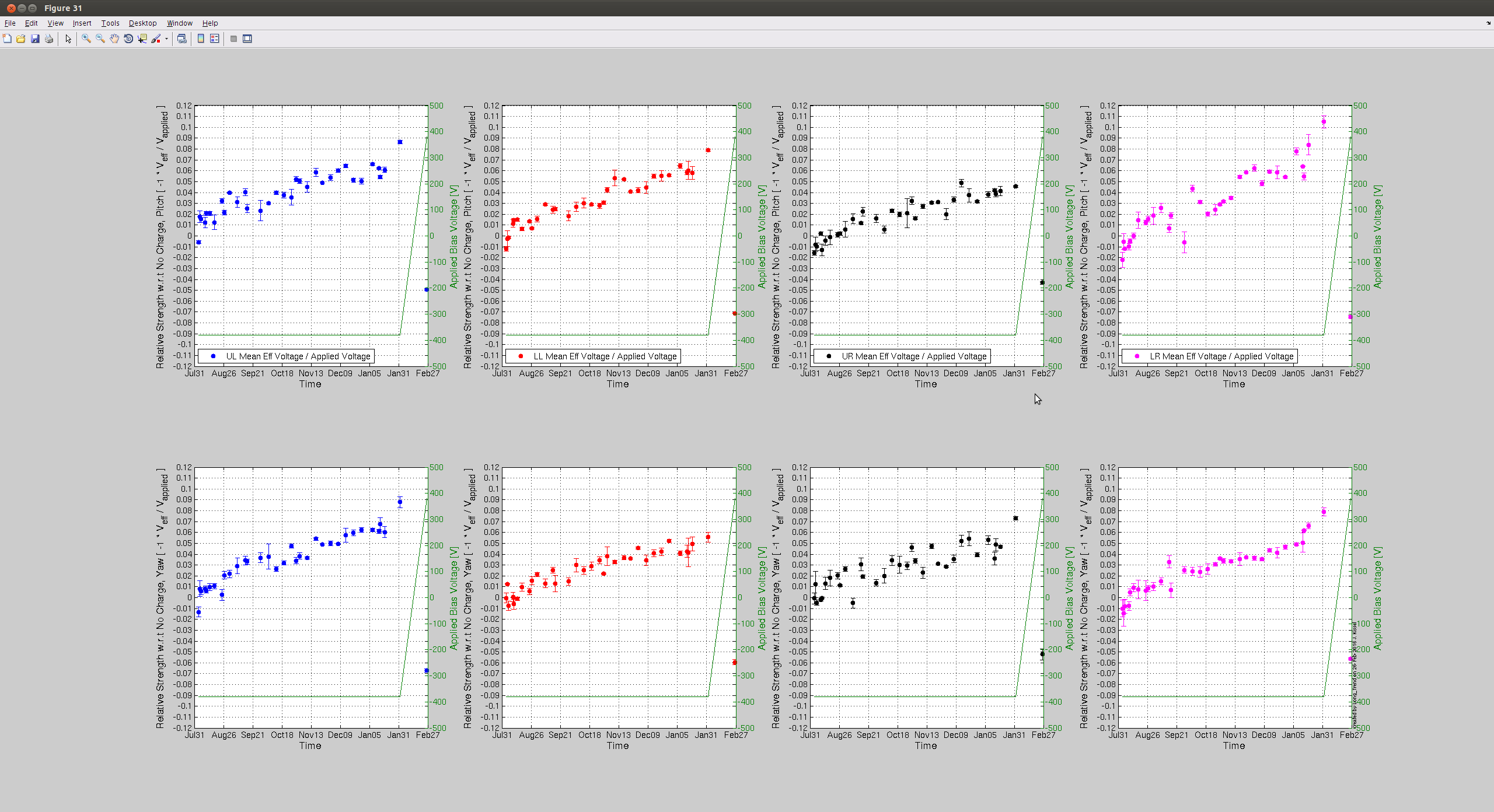
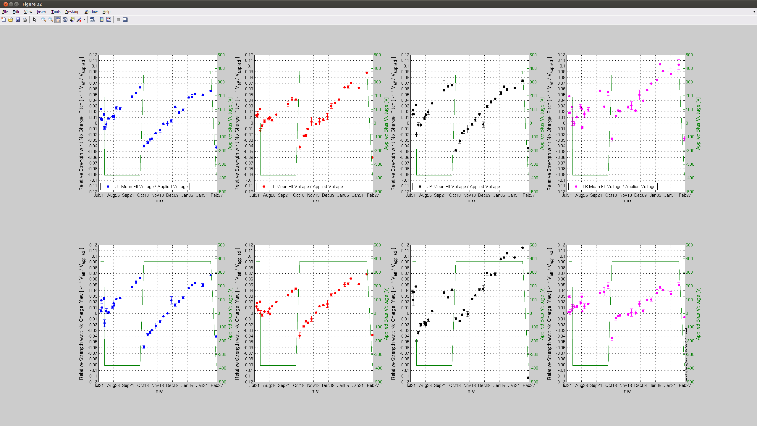
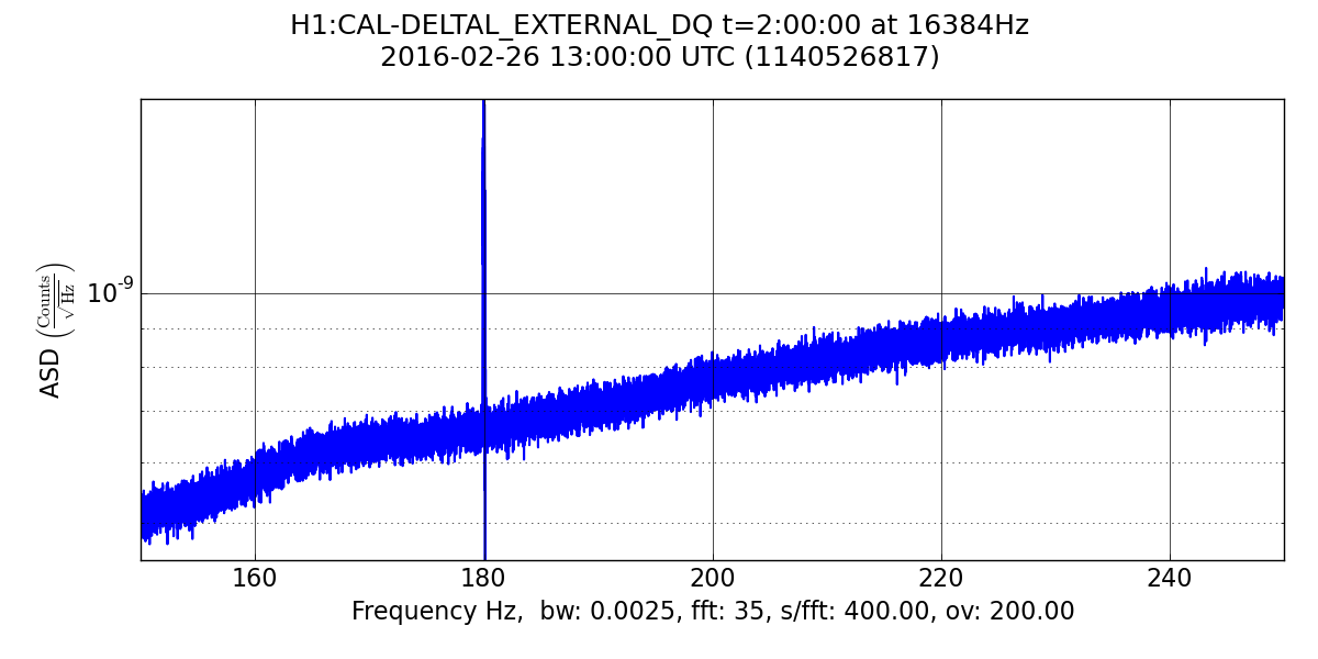
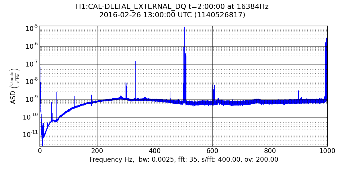
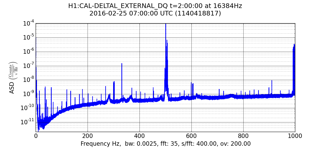
J. Kissel, C. Gray

Corey grabbed the belated charge measurements for this week. The results are attached. The message: the bias flip appears to have worked as expected, and the bias voltages are slowly creeping back to zero. This is the first effective bias voltage measurement since both bias flips on Feb 16th (the last measurement was the day before, Feb 15th). Recall after the last flip, the first few measurements we're a good indication of the eventual rate of charge / discharge, so we should continue to get weekly measurements. (And now one *more* operator knows how to do it!)

Two bits of sadness:
(1) the calibration line amplitude monitors are no longer computed. That means we can't make the continual assessment of the longitudinal actuation strength like we'd done during the run, see e.g. LHO aLOG 24547. I'm gunna ask Greg why, and if we can't restart it.
(2) Since the ESD Driver's response has changed with the deployment of ECR E1500341 on Feb 9th (see LHO aLOG 25468), the DARM loop model no longer agrees with reality, as was discovered after the bias flip -- see LHO aLOG 25604. In the rush, we gave up, didn't fix the model, and therefore didn't update the EPICs parameters that are used by the GDS pipeline calculate the time dependent actuation strengths. That means that there is no new reference time, and the pre-O1 reference time of Sept 10 2015 is still being used. Maybe that's good, maybe not. Depends on what questions you want to ask.

"Reconciling" these optical lever effective bias voltage measurements with the recent measurements of EY ring heater voltage coupling to charge *on the barrel of test mass* (see LHO aLOG 25655):
(1) Measuring the ring heater's coupling to the charge on the barrel of the test mass is *not* necessarily the same charge that the optical lever measures, which is between the gap. See discussion in T1500467).
(2) Further, having the bias voltage ON at 400 [V] during the EY measurement (see later comment LHO aLOG 25669) will certainly confuse the results. Changing ring-heater potential (the ~ few [mV] drive at 162 [Hz]) is attracting the reaction mass bias ring instead of the test mass charge along the barrel. With the now-moving reaction mass having charge as well (in between the gap, as measured by the optical levers), then one can imagine a good bit of confusion between all of the different mechanisms for charge to change the actuation strength (again, see discussion in T1500467).
Images attached to this report