Jennie W, Sheila, Elenna
In order to get data for mode-matching and for Elenna to get data to calibrate sideband heights we ran some mode scans after the SR3 heater was turned on last night.
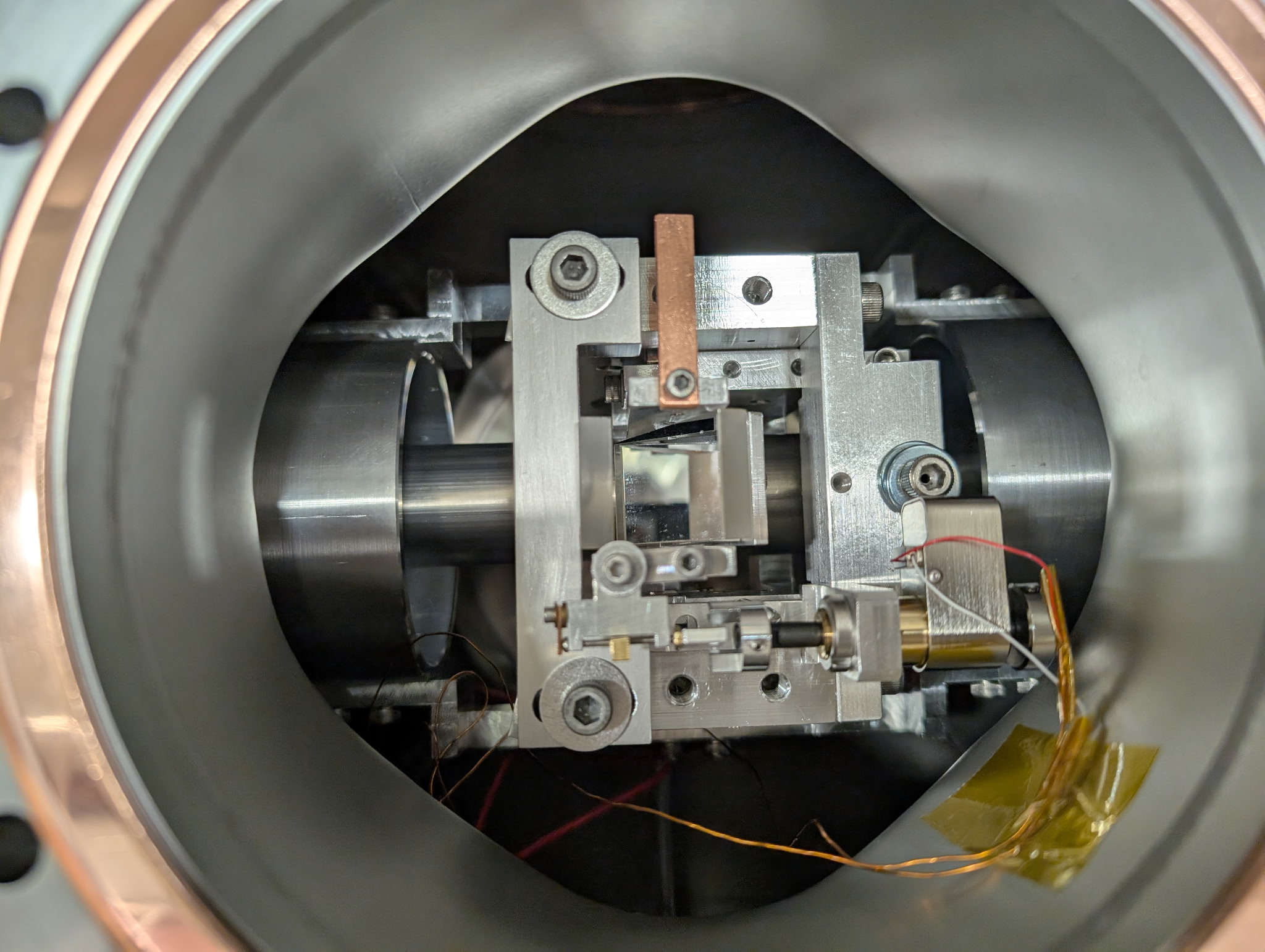
16:55:24 UTC Carried out single bounce OMC scan at 10W PSL input with sensor correction on HAM6 on, high voltage on for PZT driver in HAM6, sidebands off , SRM mis-aligned, ITMY mis-aligned, DC 3 and 4 on, OMC ASC on.
Excitation freq changed to 0.005 Hz as the top peak of the TM00 mode looked squint so could have been saturating. Lowering this frequency prevented this.
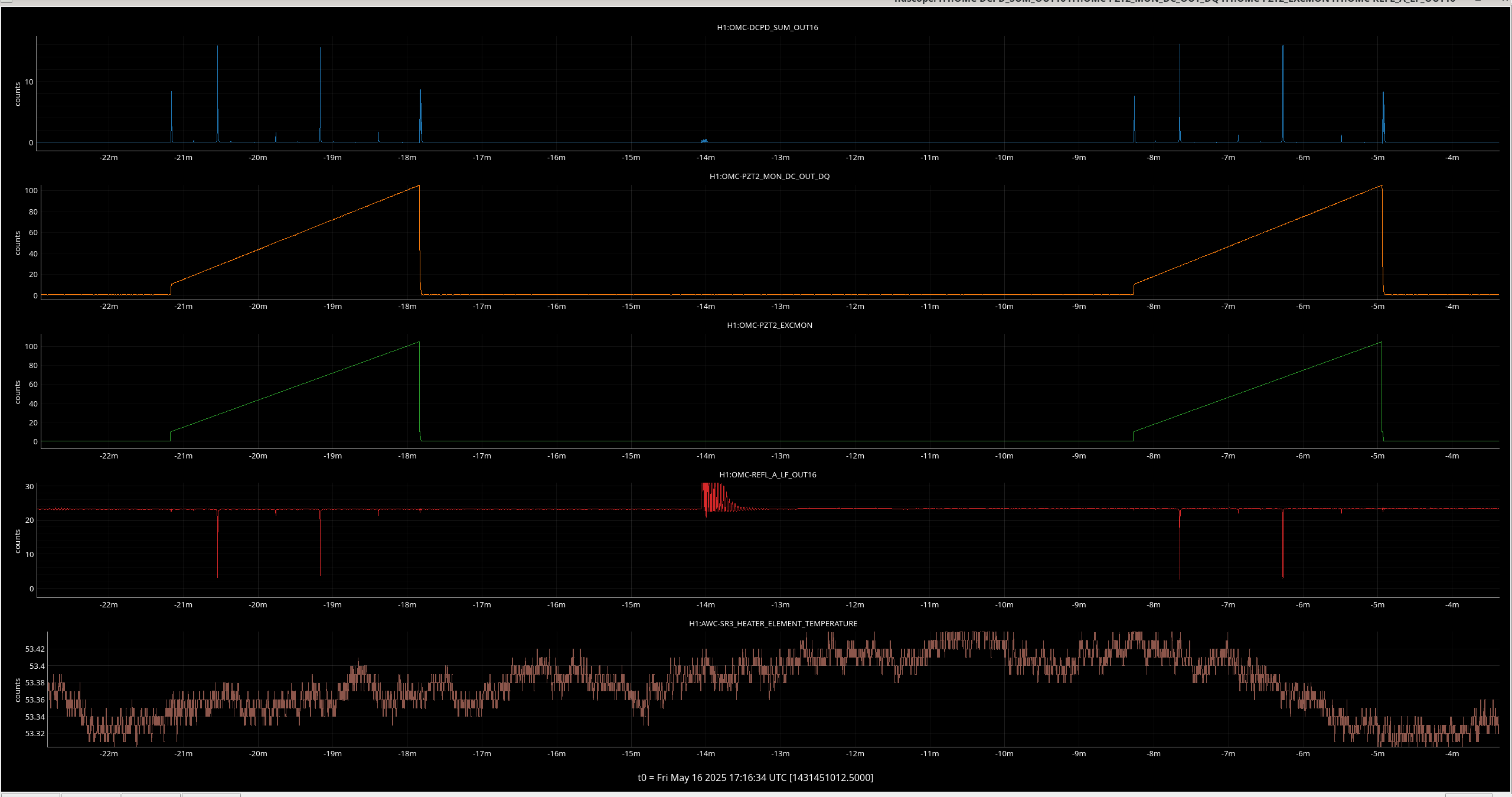
Ref 15-17 corresponds to dcpd data, pzt exc signal, pzt2 dc monitor.
Then mis-aligned ITMX and aligned ITMY (Sheila had to re-align SR2 to centre on ASC-AS_C).
Measurement starts at 17:08:18 UTC.
Ref 18-20 corresponds to dcpd data, pzt exc signal, pzt2 dc monitor.
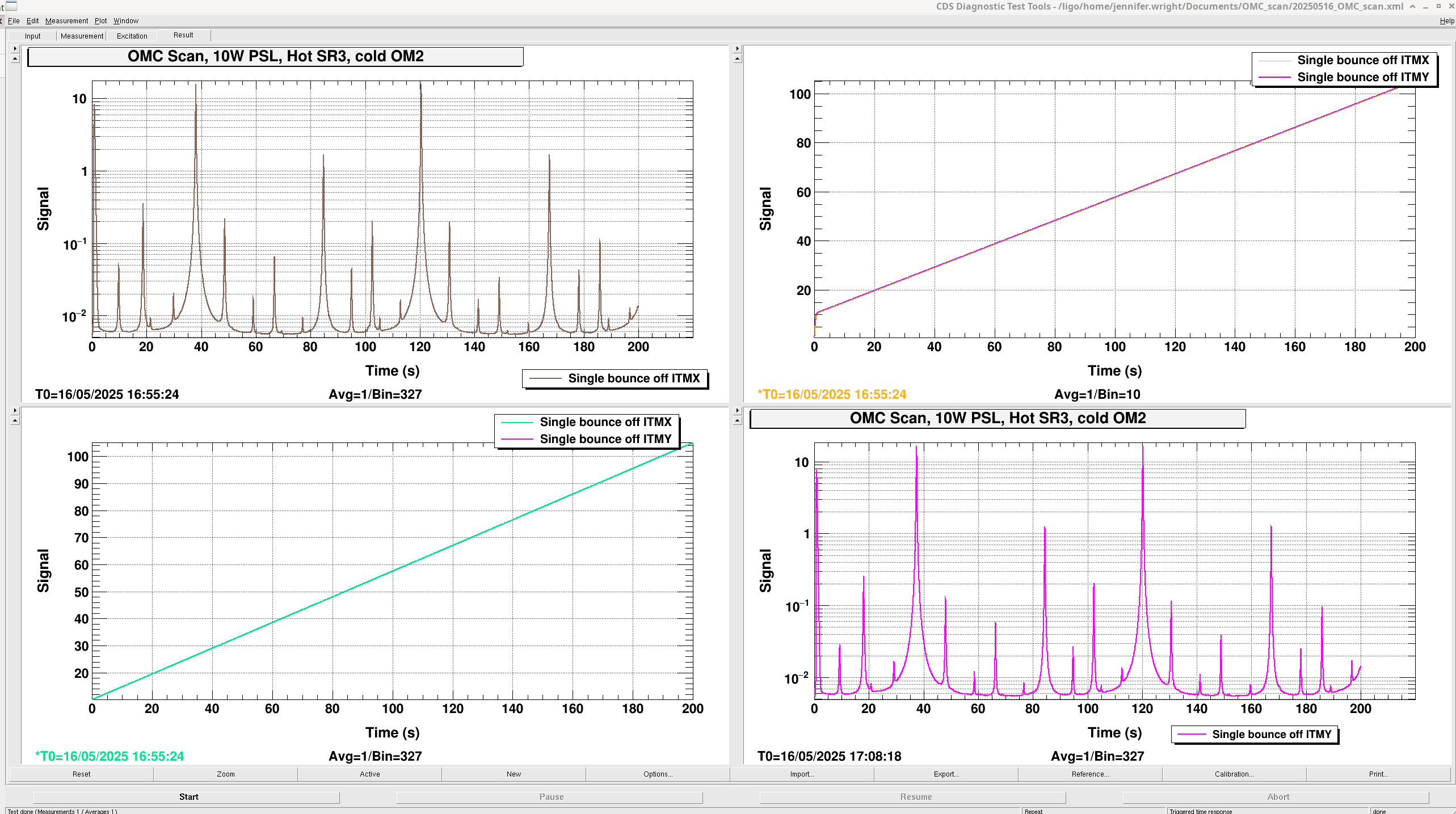
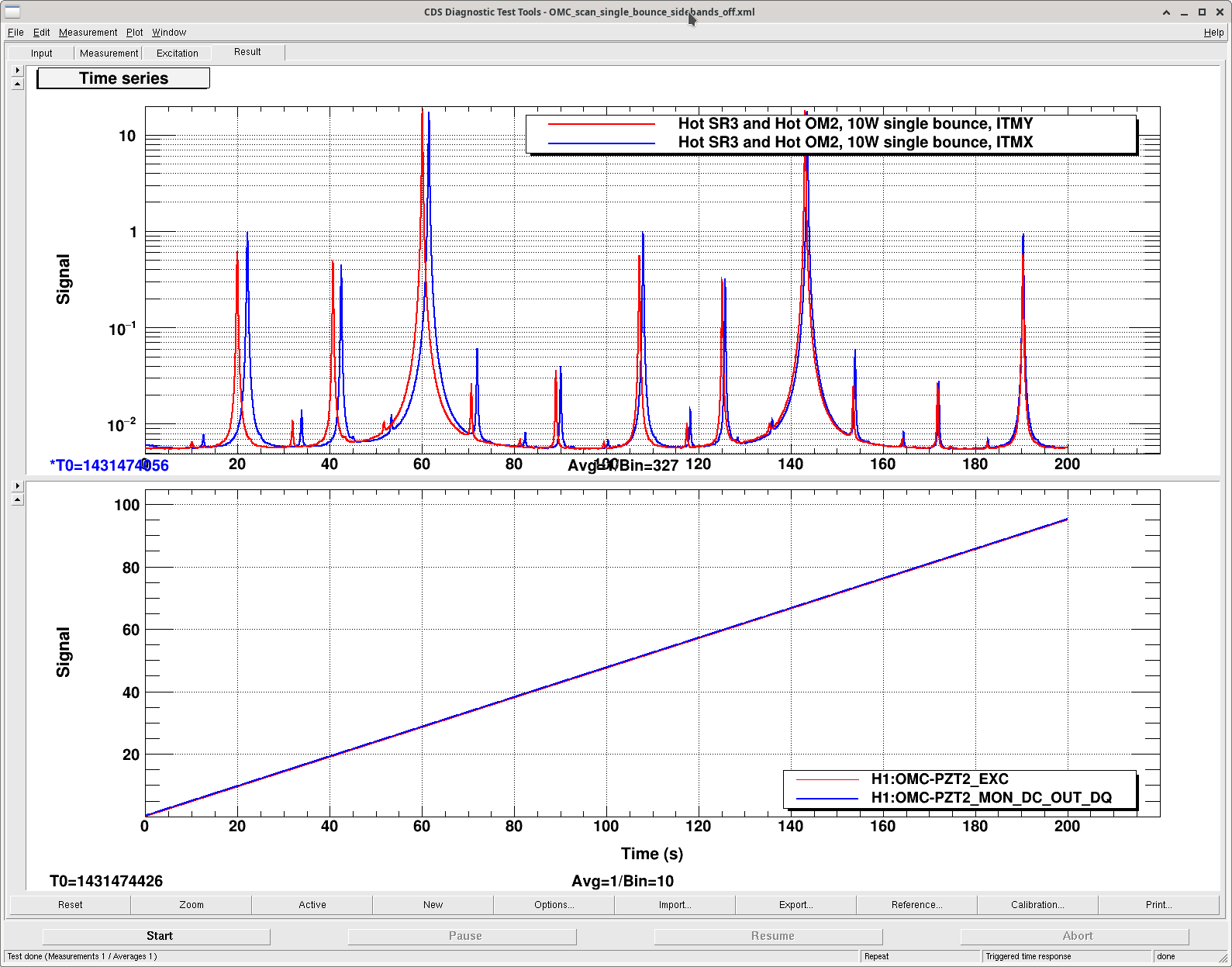
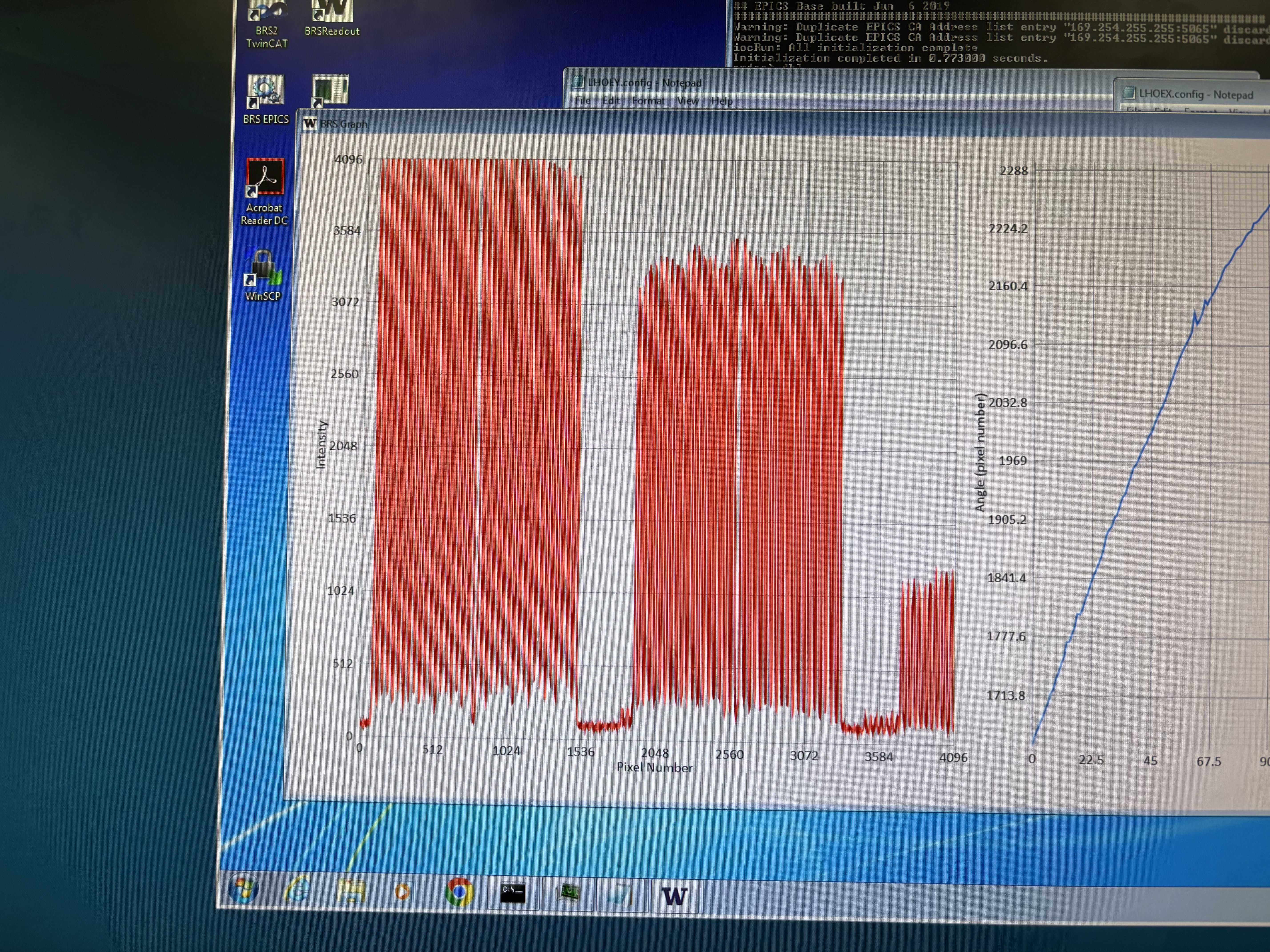
Traces saved in 20250516_OMC_scan.xml. The top left plot is the first scan bouncing beam off ITMX, the second scan is the bottom right bouncing off ITMY.
The top right is the two plots of the PZT2 DC voltage monitor. That is, the current voltage applied to the PZT. The bottom left is the plot of the voltage ramp applied to the PZT2 on the OMC for this measurement.
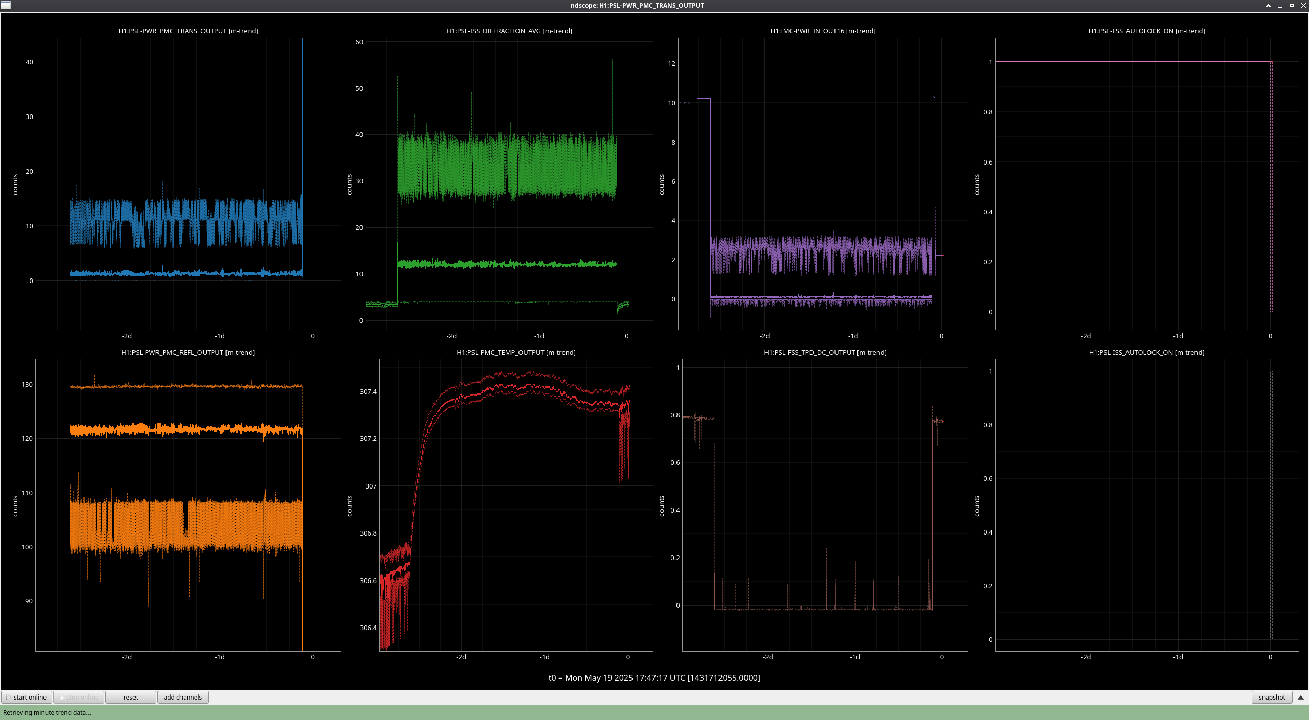
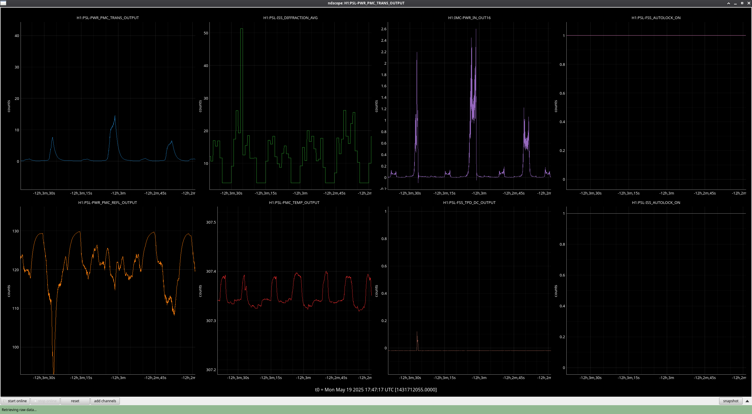
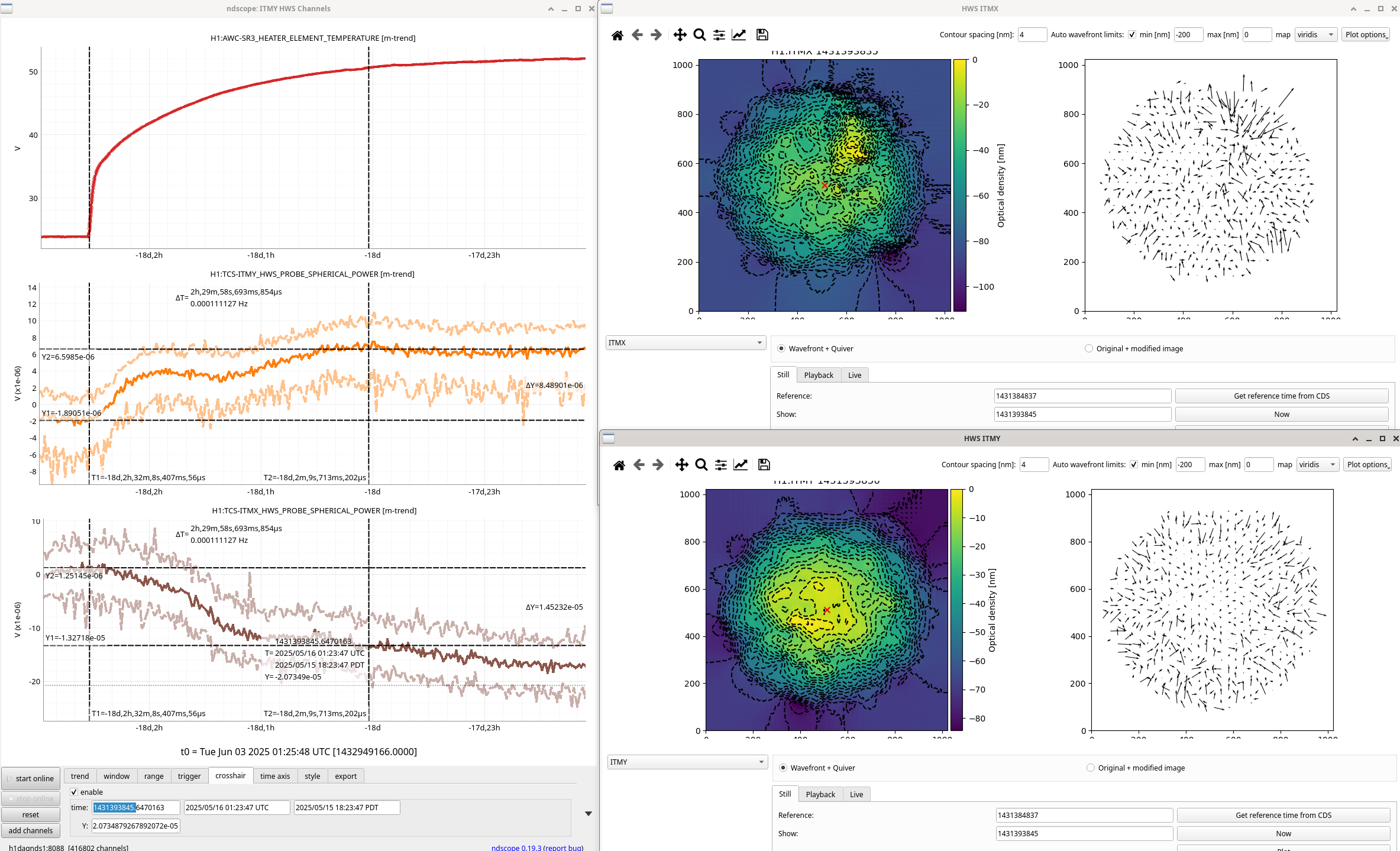
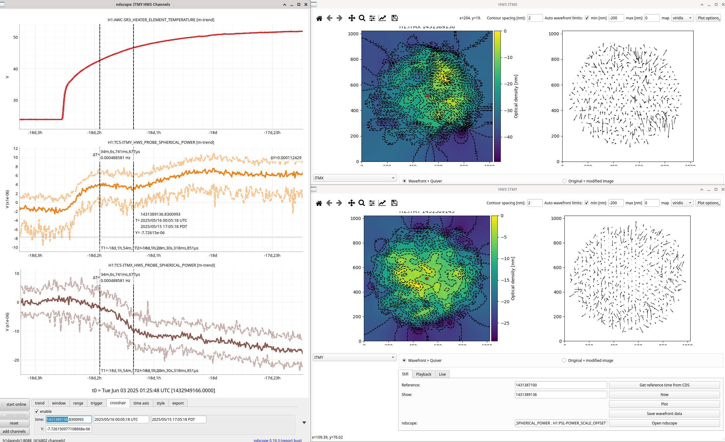
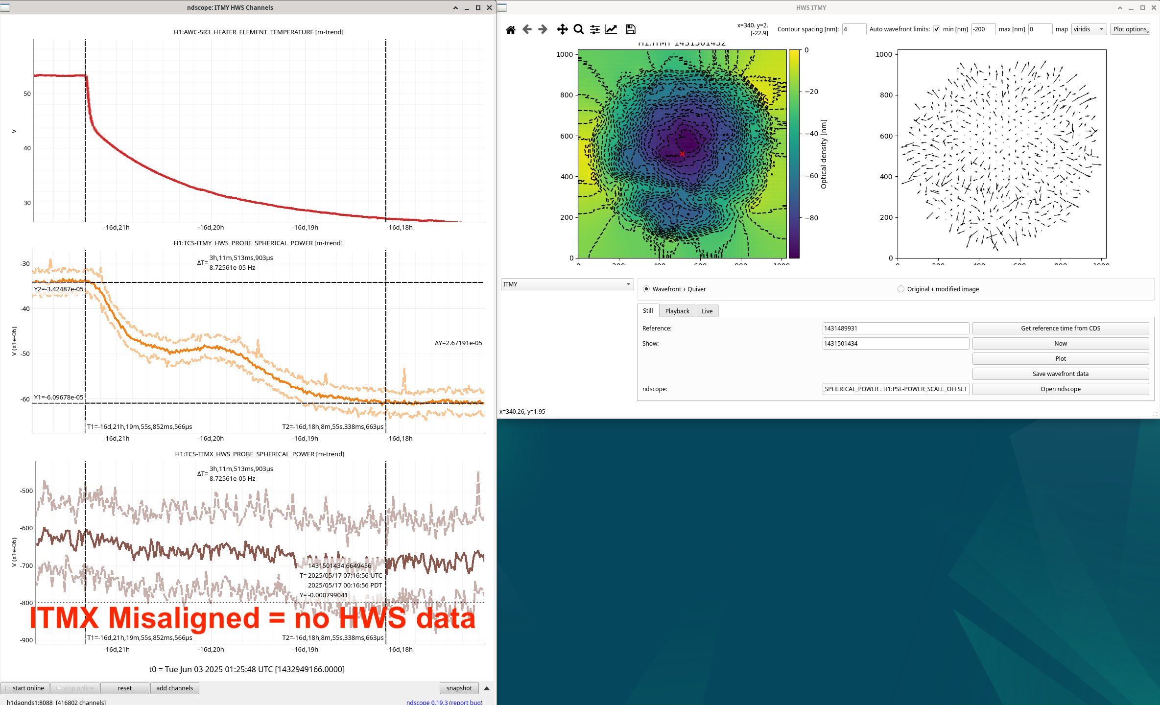
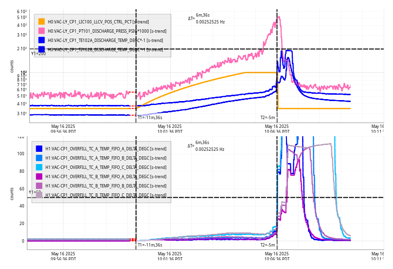
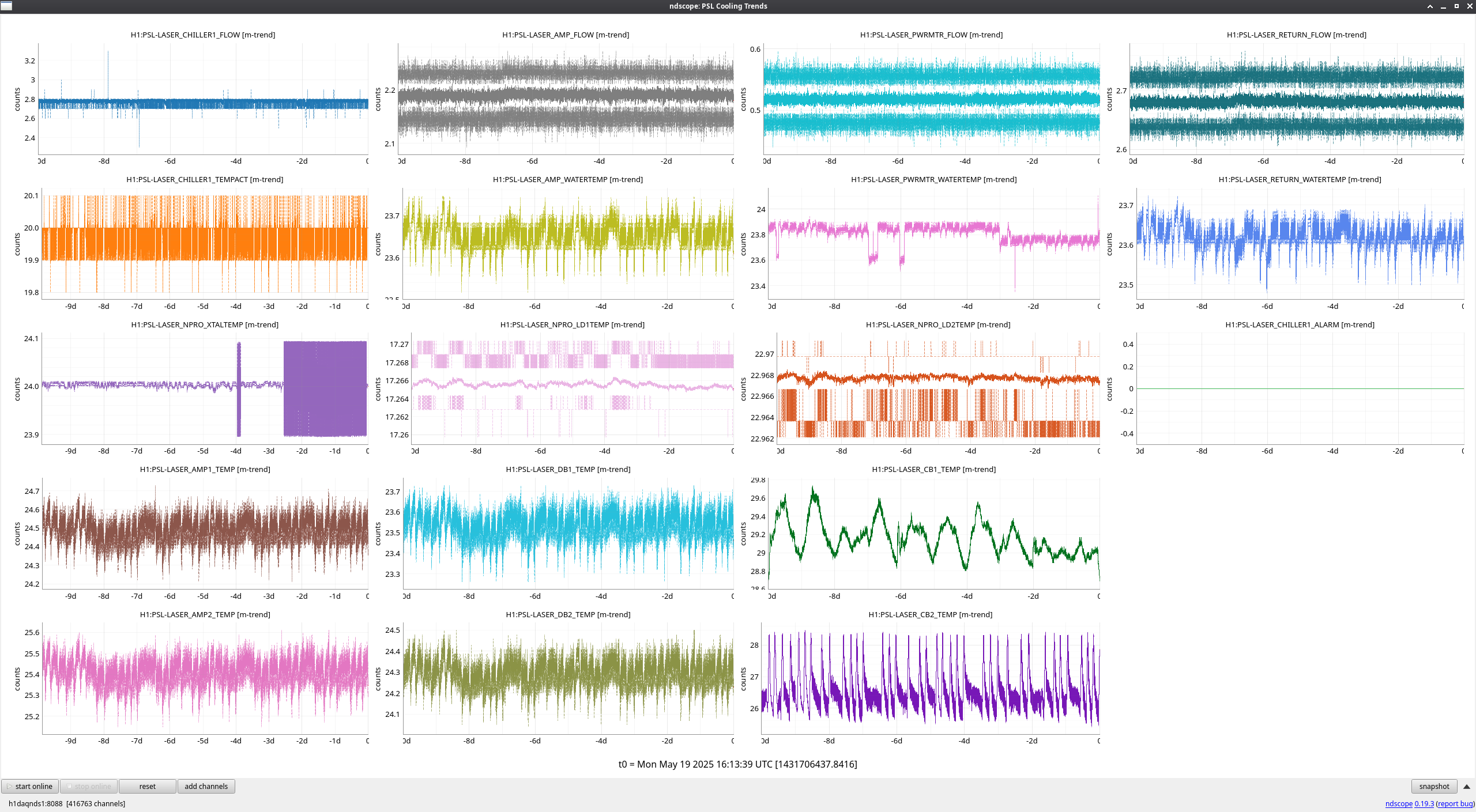
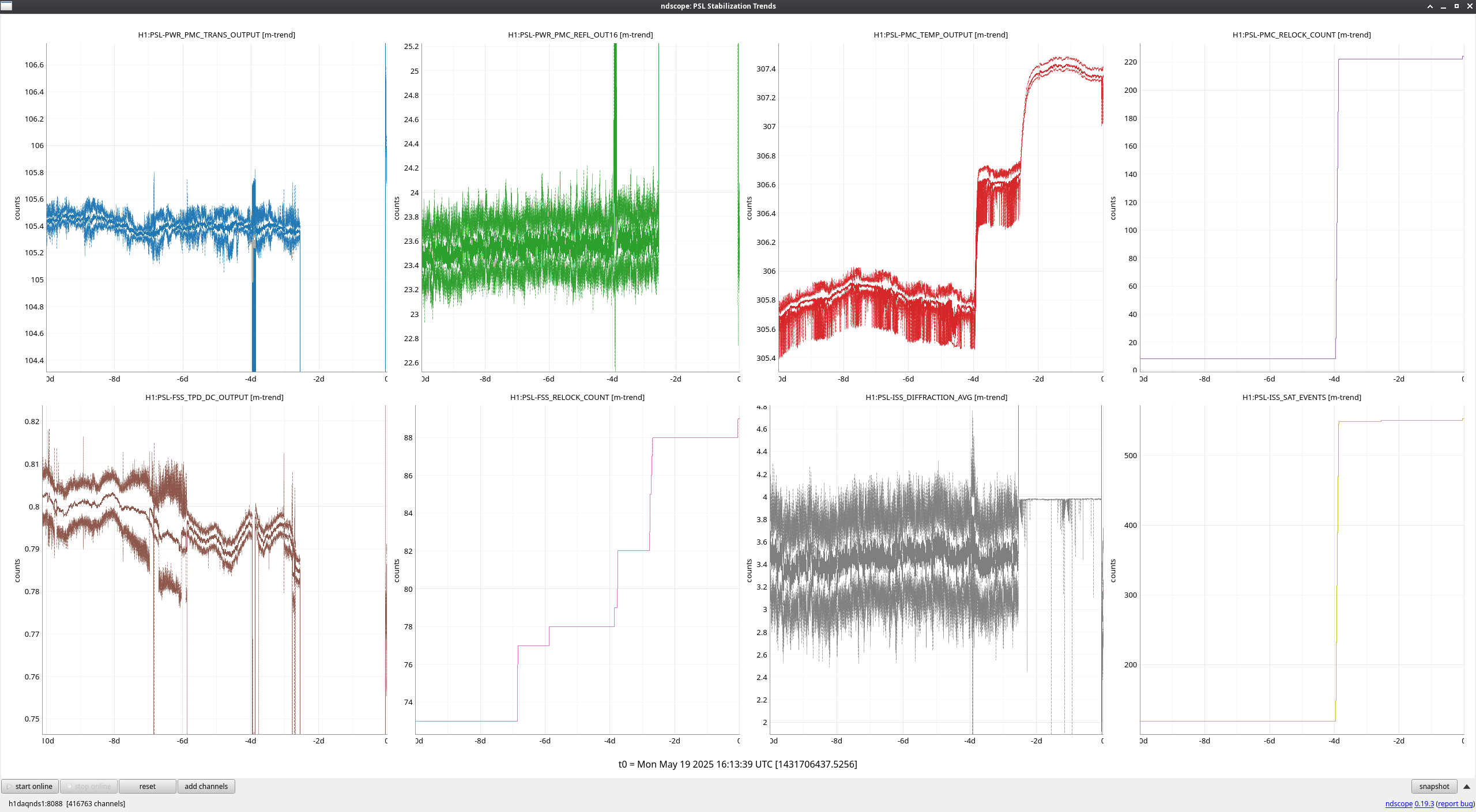
The ndscope attached shows the power in mA transmitted through the OMC on the top, then the PZT used for the scan DC voltage underneath, then the input PZT voltage underneath that, then the reflected power from the OMC in mW, then at the bottom the SR3 heater element temperature in degrees.
Elenna did two more scans in single bounce with sidebands back on and different modulations depths in each.
