Cao, Elli
To measure the SRC gouy phase, we need to move the BS and PR2 optics in yaw and know the angle we move them to at least 5% (but ideally more like 2%). So today we checked the calibration of these optics' alignment sliders using the ETMY baffle PDs. We have used the method which was previously used to calibrate the BS optic align sliders (alog 14321), although we have taken extra care to loacte the center of the baffle PDs, as we are particularly interested in understanding the accuracy of this measurement. Just to be clear, we are not making any changes to the alignment slider gains, we are simply measuring how good the current ones are.
Method:
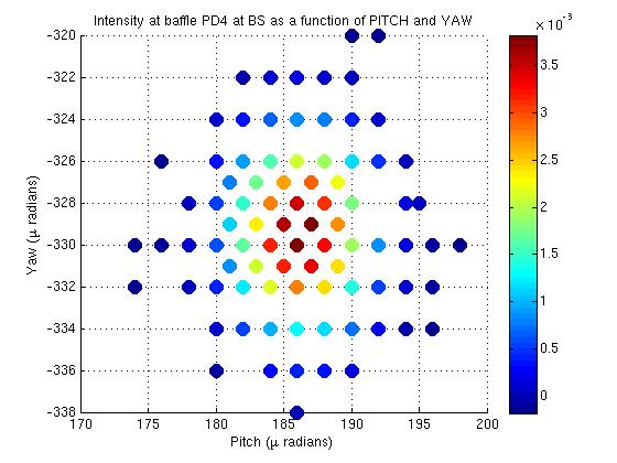
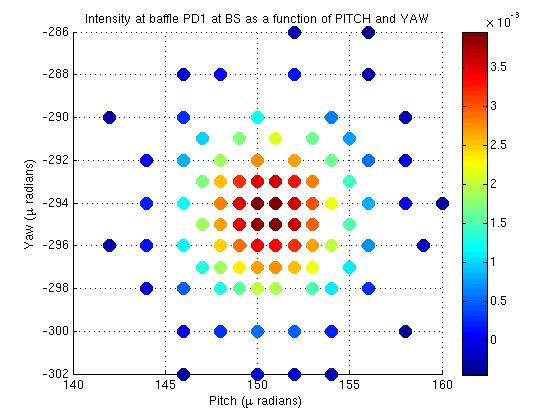
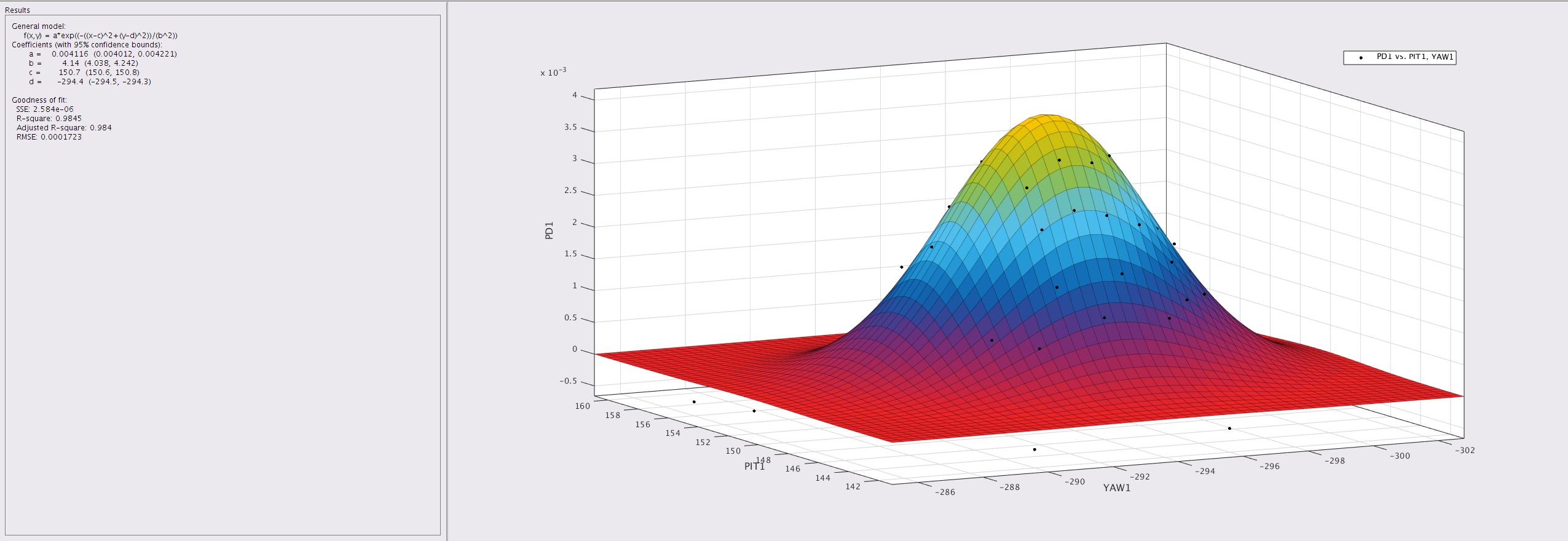
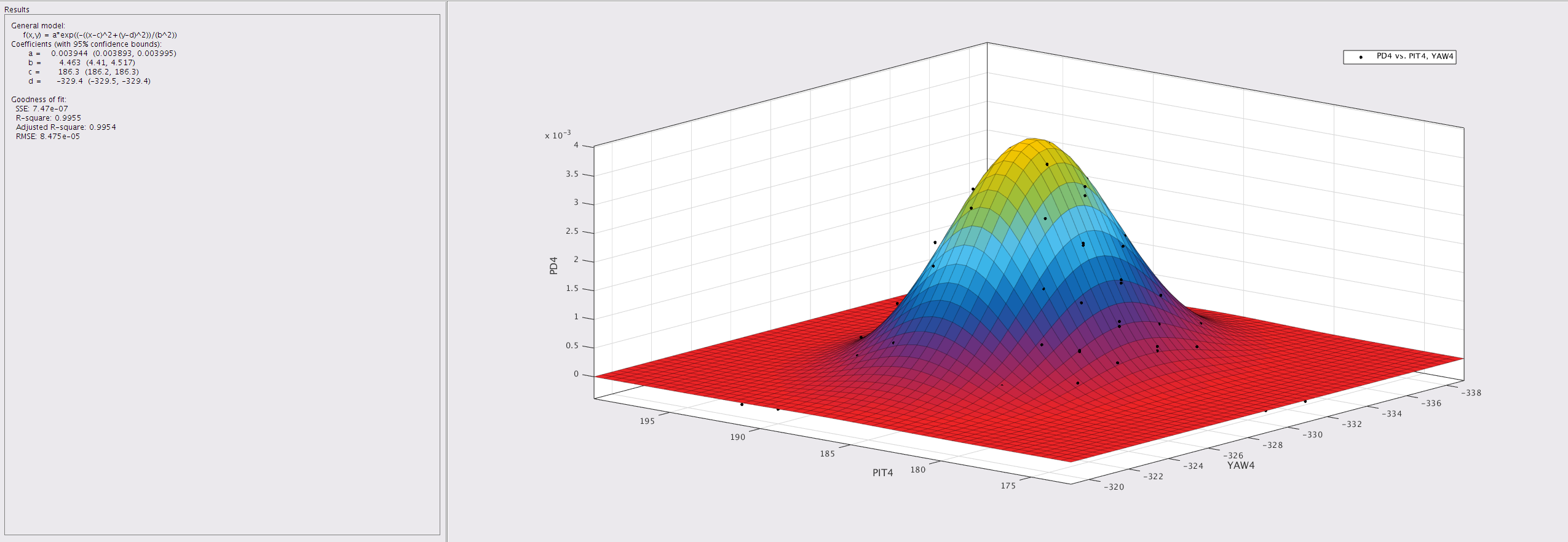
The BS was moved in pitch and yaw to direct the PSL beam onto each of the ETMY baffle PDs (PD1 and PD4). PRM, SRM, ITMs, ETMs and TMSs were misaligned to prevent flashes from other optics from corrupting the baffle PD signal. Once the PSL beam was directed onto a baffle PD, we moved the BS around and plotted BS location vs intensity. We fit gaussian profile to this plot to pinpoint the BS slider values for when the beam is centered on each of the baffle PDs. (Attached are the plots of slider value vs PD power and the fited gaussian, for the BS).
This procedure was repeated using the PR2 to direct the beam onto each baffle PD.
Results:
From the fits of slider value vs intensity of the PD, we get the following optic_align values when the BS/PR2 optics were pointed at the center of the baffle PDs:
|
|
BS |
|
|
P "urad" |
Y "urad" |
|
ETMY PD1 |
150.7+/-0.1 |
-294.1+/-0.1 |
|
ETMY PD4 |
186.3+/-0.1 |
-329.4+/-0.1 |
|
Difference in optic align values when moving from PD1 to PD4 |
35.6+/-0.2 |
35.3+/-0.2 |
|
Multipied by 2 for angle beam moves to go from PD1 to PD2 |
71.2+/-0.5% |
70.6+/-0.5% |
We can check the calibration of these sliders by comparing to the angle the beam moves through to move from PD1 to PD4, as calulated from the geometry of the interferometer. Accordong to Jeff and Gerado (alog 14321, D1200296), the baffle PD locations are 11.329 [inches] = 0.288 [m] apart in vertical, and 11.313 [inches] = 0.287 [m] apart in horizontal. With a 3994.5m long arm (LHO aLOG 11611), and 4.986 [m] for the distance between the HR surface of the BS and the back of the ITMY CP, through the thin CP, through the ITMY to the HR surface of ITM, respectively (D0901920), that's a lever arm of 3999.5 [m]. Hence, a displacement of
BS P 0.288 [m] / 3999.5 [m] = 72.01 [urad]
BS Y 0.287 [m] / 3999.5 [m] = 71.76 [urad]
The alignment offset slider gains can therefore be corrected by
BS P 72.01 / 71.2 = 1.011 [urad/"urad"]
BS Y 71.76 /70.6 = 1.016 [urad/"urad"]
or
BS P 0.989["urad"/urad]
BS Y 0.984 ["urad"/urad]
Which means the BS calibration is pretty bloody good. Go team!
Checking the calibration of the PR2 alignment sliders can be done similarly, provided we take into account the extra distance from PR2 to PR3 to BS, and the ROC of the PR3. This looks like a job for tomorrow.
|
|
PR2 |
|
|
P |
Y |
|
ETMY PD1 |
1699+/-1 |
4475+/-1 |
|
ETMY PD4 |
1957+/-1 |
4180+/-1 |
|
Difference in optic align values when moving from PD1 to PD4 |
258+/-2 |
295+/-2 |
We broke the lock this morning to do this measurement. We have returned all optics to where they were and are leaving the interferometer in the down state (I had a shot at relocking but I've been away too long it appears :( ).