This is yet another followup of Kiwamu's cage servo followup: https://alog.ligo-wa.caltech.edu/aLOG/index.php?callRep=25416
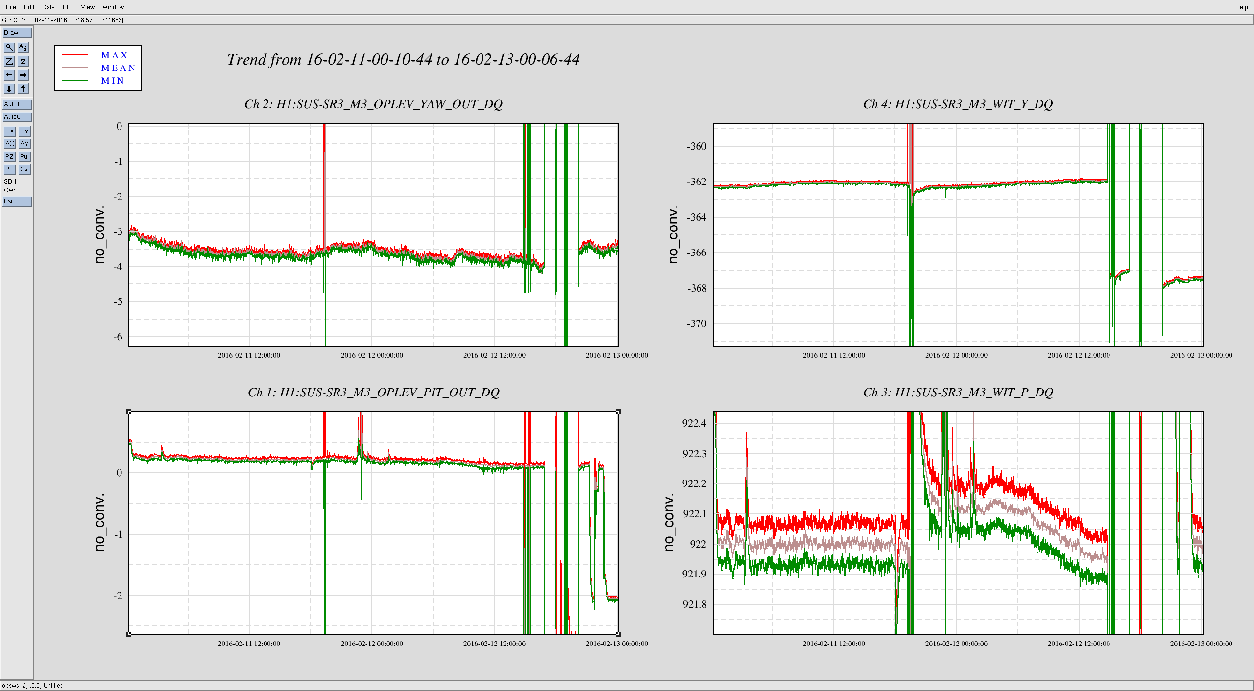
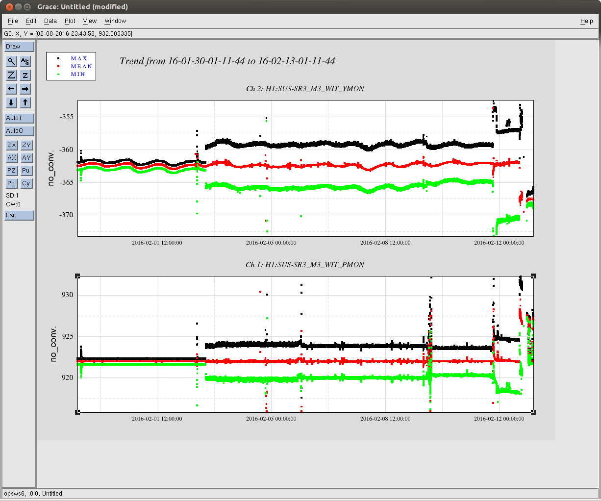
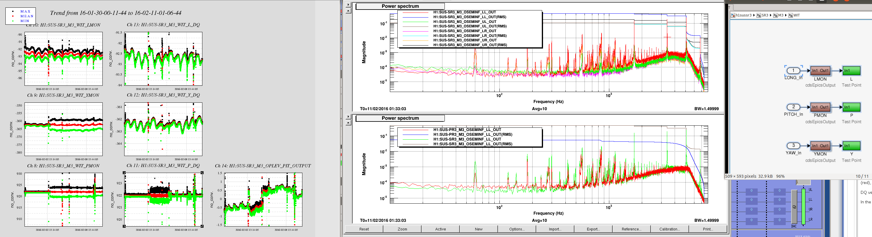
In the attached left panel is a 12-days trend of SR3 signals. Left column is the EPICS version of M3 witness sensors, and PMON is used for the cage servo. Middle column is a DQ-version of the same signal.
At first YMON and PMON were going happy together with DQ version, but at around Feb 02/03 midnight UTC, PMON and YMON got huge at the same time the cage servo went crazy, but WIT_Y_DQ didn't feel it. Later when Kiwamu turned down the cage servo gain, WIT_P_DQ (middle bottom) went back to normal-ish but PMON and YMON didn't.
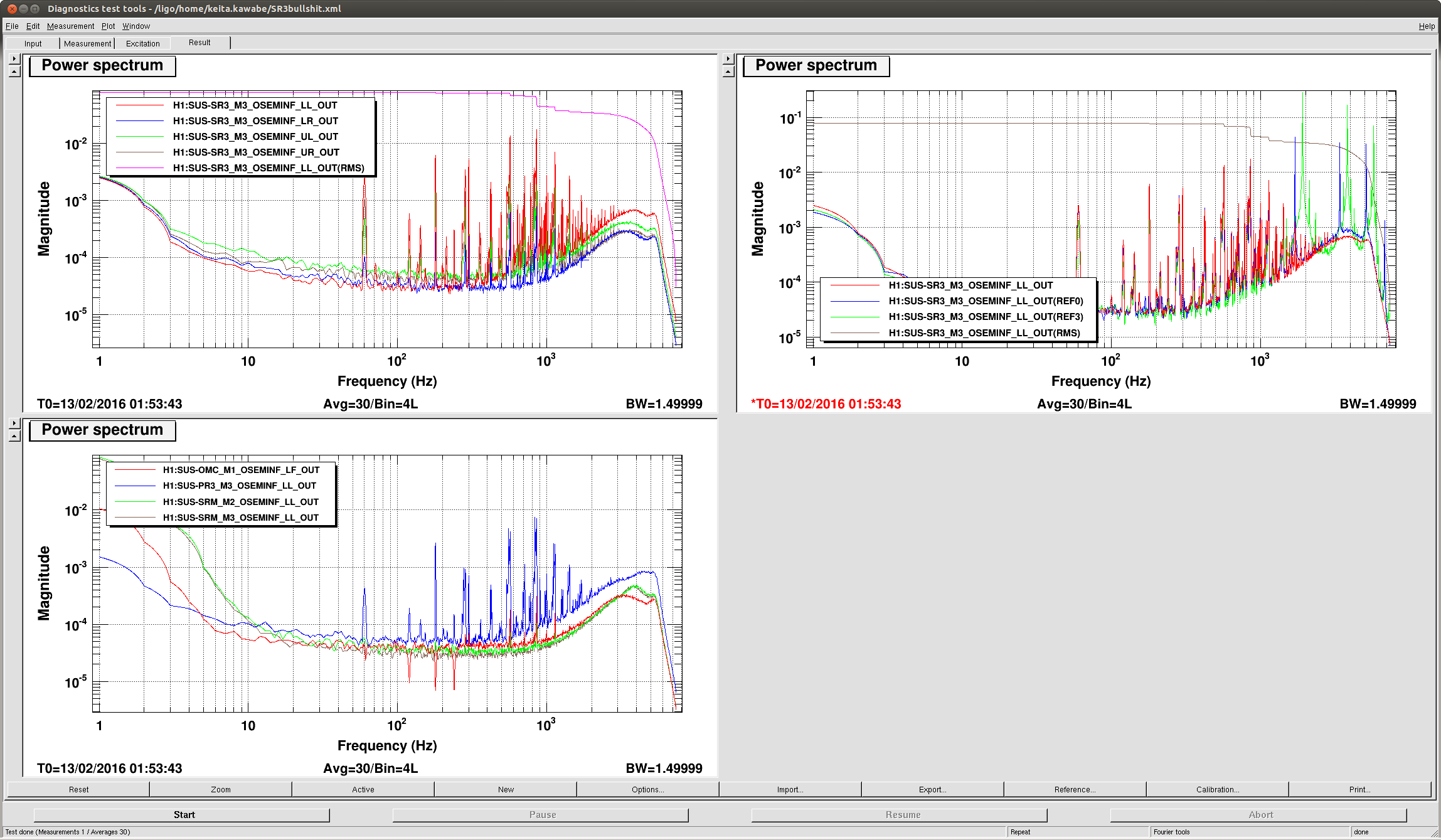
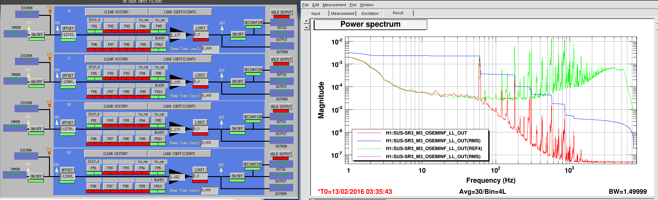
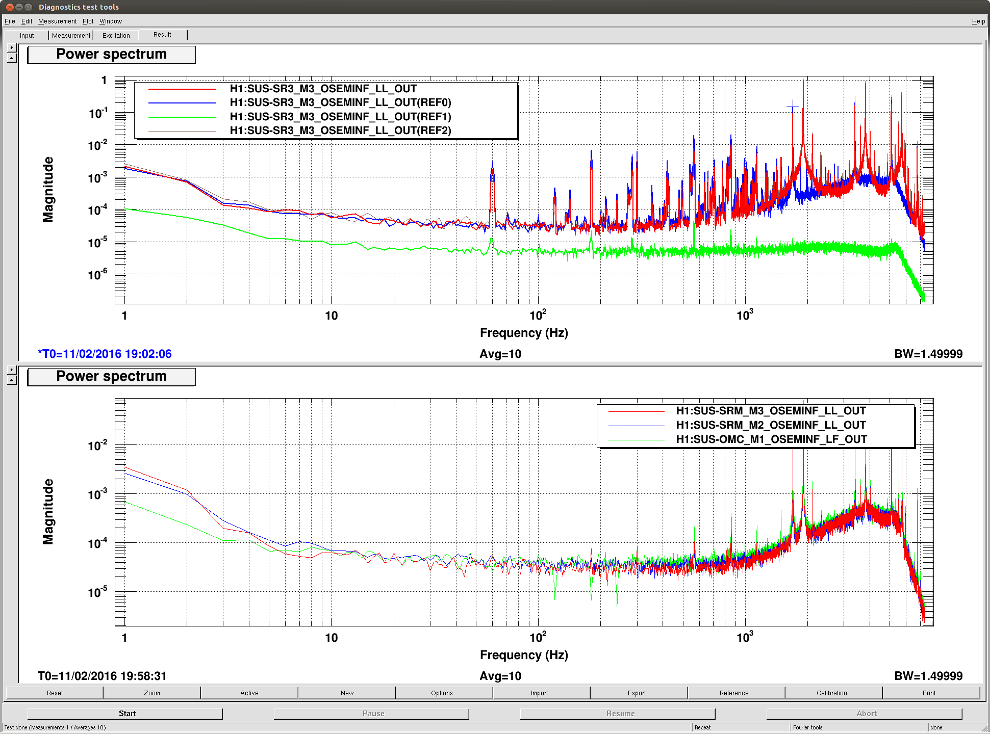
It turns out that when you look at non-DQ version of these signals (attached middle panel), there are huge lines in all four M3 OSEMs of SR3 at 1.7kHz and its harmonics, totally dominating the RMS (top). Bottom plot shows the comparison between SR3 (green) and PR3 (red), and PR3 doesn't show any of these huge lines.
DQ version is decimated by the frontend, but it seems like PMON (as well as YMON and LMON) are just sparsely sampled version of the fast signals, no filter modules therefore no decimation, thus the high frequency junk directly goes into low frequency (right panel).
In the past, the solution for oscillating satellite amps was to power-cycle them repeatedly until the oscillation stops.