Svn up'd LHO's common guardian masterswitch and watchdog folders:
hugh.radkins@opsws1:masterswitch 0$ svn up
U states.py
Updated to revision 12509.
hugh.radkins@opsws1:masterswitch 127$ pwd
/opt/rtcds/userapps/release/isi/common/guardian/isiguardianlib/masterswitch
hugh.radkins@opsws1:masterswitch 0$
hugh.radkins@opsws1:masterswitch 0$ cd ../watchdog/
hugh.radkins@opsws1:watchdog 0$ svn st
hugh.radkins@opsws1:watchdog 0$ svn up
U states.py
Updated to revision 12509.
I restarted HAM6 and tested by disabling an output leg. The trip appeared to execute the functions as expected-I did not notice any problem. Restarted HAM5 and tested, it too turned off the FF and reduced the GS13 gains as expected, no problem noticed. Restarted HAM4 but did not test (by tripping the platform.)
Restarted HAM3 after enabling the GS13 Switching feature as I wanted to test the problem of the guardian being unable to turn the GS13 gain up without tripping the platform. This is where I noticed the problem.
When guardian turned up the GS13 gain, the HAM3 tripped and it successfully turned off the FF and lowered the GS13 gains but it left the DAMPing loops engaged. I thought the restart of the guardian may have been responsible for this behaviour. I cleared the trip but did not turn off the DAMPing path first. The ISI did not trip until the GS13s were again toggled to high gain but this time, the DAMPing path was turned off as I would expect. Okay, maybe first time around problem. Cleared the trip and again the platform tripped when the GS13 gain changed and again the DAMPing path was left on. I repeatd and again the DAMPing path was left on. I disabled the GS13 Gain Switching feature and we made it to isolated and I set the GS13 gains to high with the Command Script.
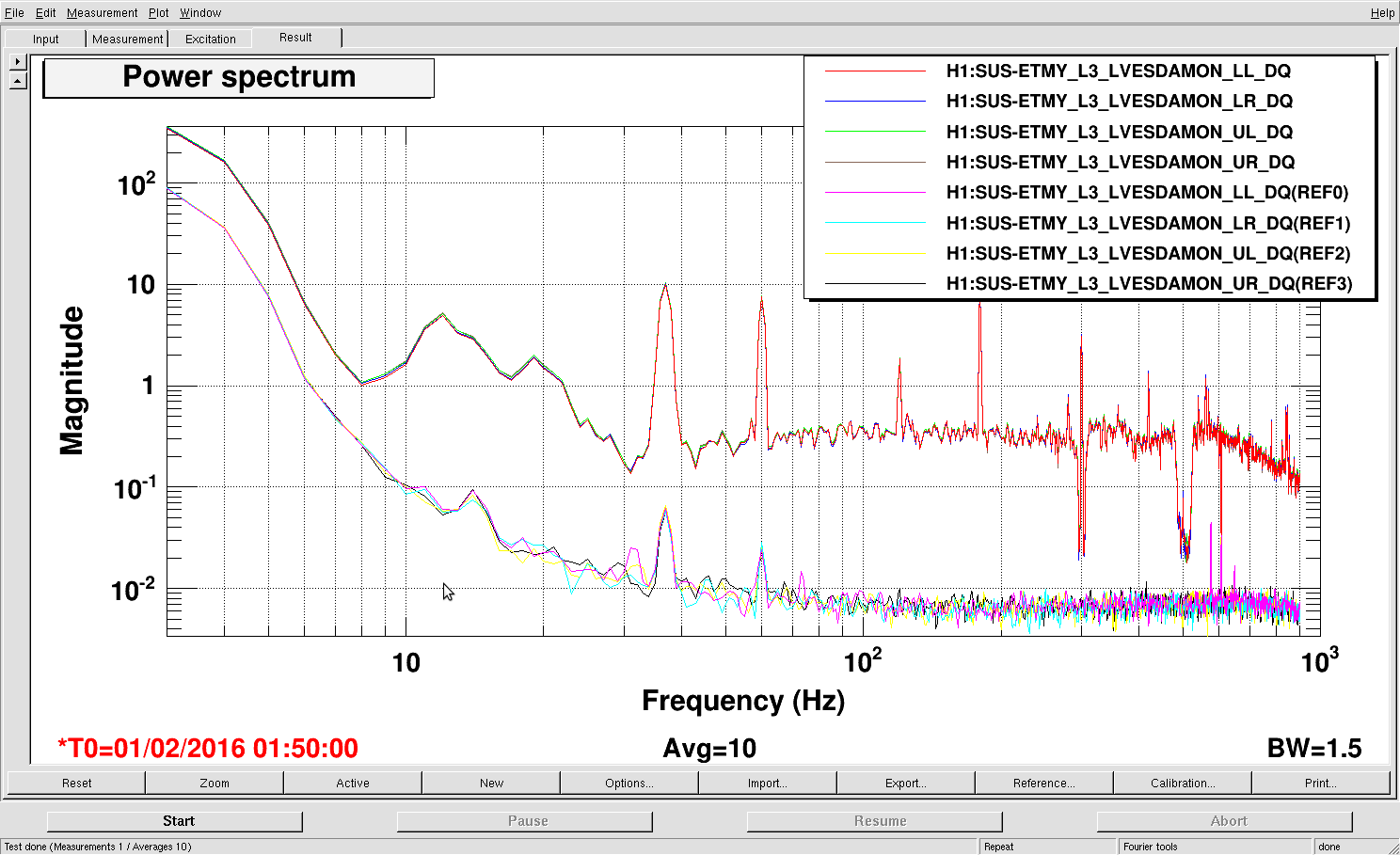
I've repeated the test on HAM5 and there too, DAMPing path remained on.
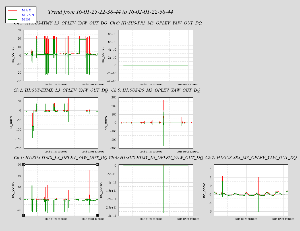
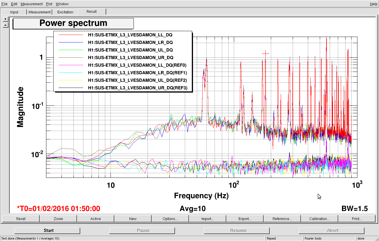
Meanwhile ITMX tripped due to LVEA activity, DAMPing path not turned off and this guardian has not been restarted with the new update. Repeated this on ITMY and it too left the DAMPing path enabled. Okay, it looks like this DAMPing problem is not related to the current code upgrade.
I will continue to restart the guardian with this current upgrade though as the turning off of the GS13s when tripped is a good thing and generally, the platform can deal with untripping the watchdog with stuff coming out of the DAMPing path, as long as the GS13 are in low gain. And since HAM2 & 3 can't handle guardian gain switching, they must have the gains toggled manually.
I've restarted all the LHO ISI Guardians. Tested the function/features and problems and they are all present on ITMX ISI too.
I modified watchdog/states.py to accomodate for this additional request to the T150549 update. The update was comited to the SVN: