We've continued measuring the beam spot positions once a week as part of Tuesday maintenence.
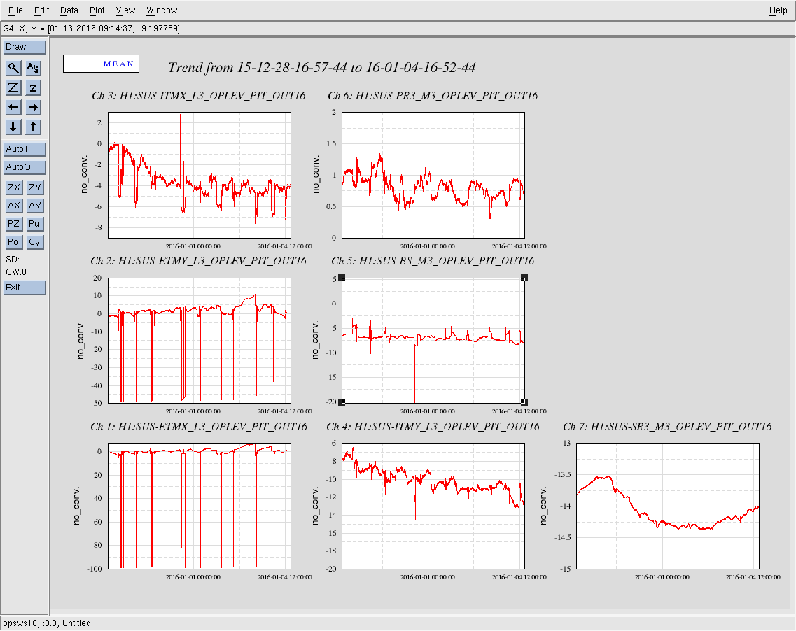
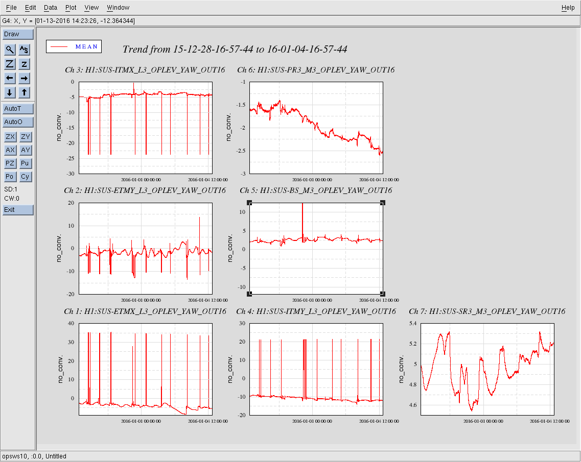
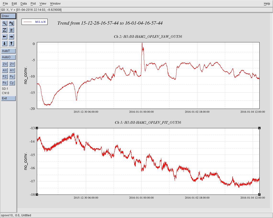
The 2 pdfs below are different views of the same data set. The first set of plots is the data on x-y grids, so you can really see how little our spots are moving. The second set of plots is the data as a function of time. Some of the pitch values are changing more now than they were back in October, but the maximal excursions are still only about 2mm away from the means.

Here's the same data, but with more features in the presentation.
The color indicates the time between lock acquisition and the measurement. Darkest blue is 0 minutes, and brightest pink is 30+ minutes, with a gradient in between.
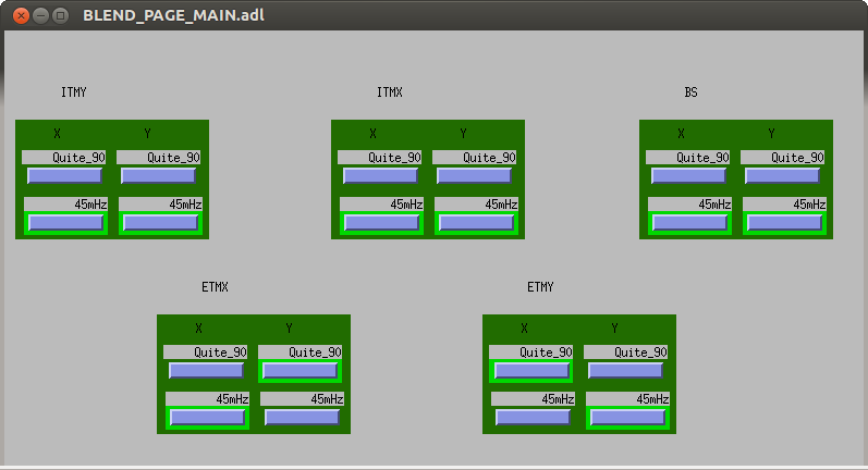
The marker shape now (per JimW's request) indicates the ISI blend state, as a check to see if changing the blends changes the alignment. Circles indicate both x and y axes of the ISI are on the Quite_90 blends, diamonds indicate both axes on the 45mHz blends, and square markers indicate that the beamline axis is on the 45mHz and the orthogonal axis is on the 90mHz blend. I conclude that the ISI state has no noticeable effect on the beam spots.