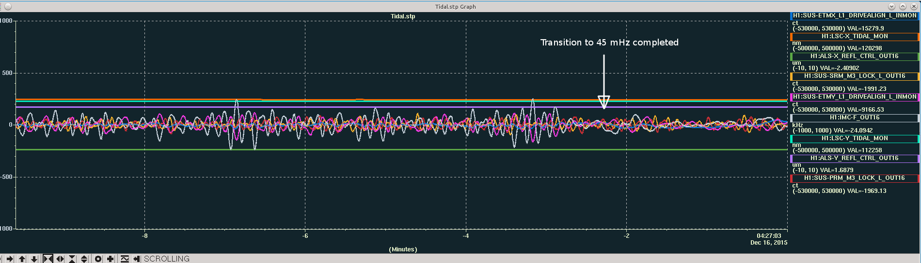
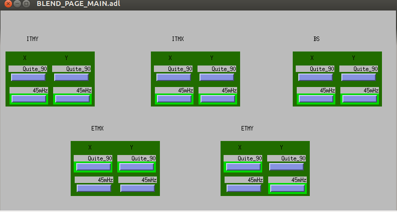
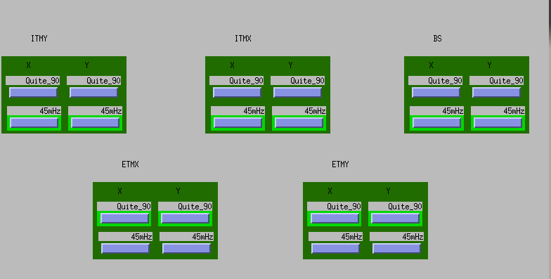
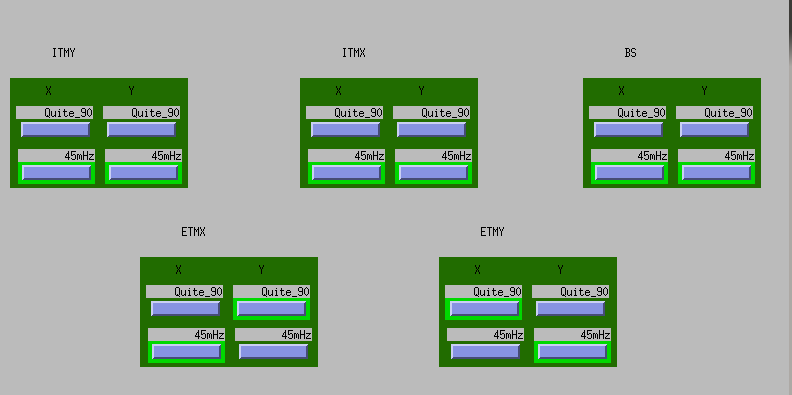
**Short version: Increased RY input motion (maybe HEPI, maybe wind/ground) causes ISI X loops to ring up when running 45mhz blends. The suspension/tidal is not the cause. The 90mhz blends seem to be immune to this. Other than using 90mhz blends, I'm not sure how to fix the ISI's configuration, short term to prevent the ISI from ringing up. But we should put a StripTool of the end station ISI St1 CPS locationmons somewhere in the control room so operators can see when ground tilt has rung up an ISI. Alternatively, we could add a notification to VerbalAlarms or the DIAG node when an ISI has been moving something like 10 microns peak to peak for several minutes.
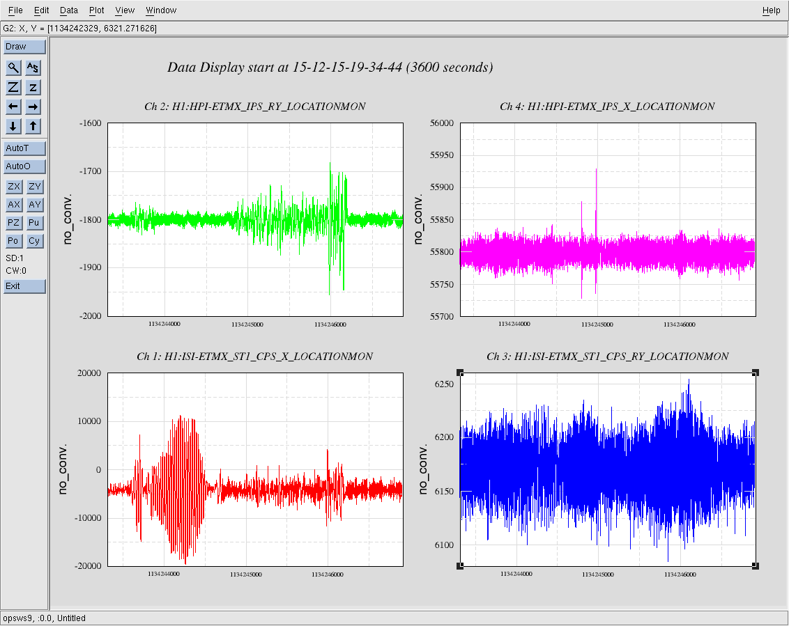
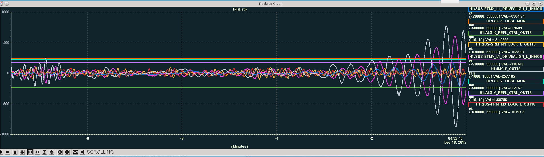
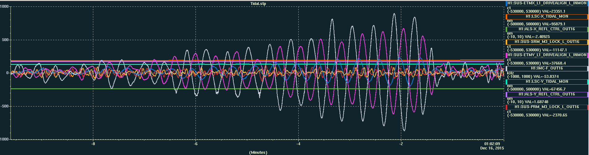
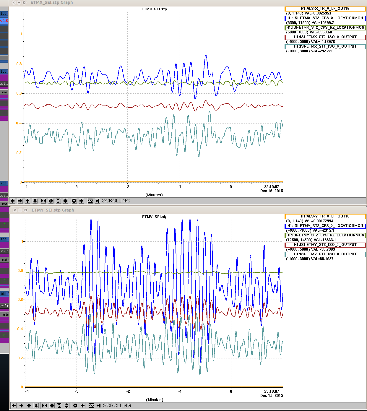
This morning while the IFO was down for maintenance, Evan and I looked at ETMX to see if we could figure out what is causing the ISI to ring up. First we tried driving the L1 stage of the quad to see if some tidal or suspension drive was the cause. This did not have on the ISI, so I tried driving on HEPI. When I drove HEPI X, the ISI rang up a bit, but no more than expected with the gain peaking of the 45mhz blends. When I drove HEPI in RY, however, the ISI immediately rang up in X, and continued to ring for several minutes after I turned the excitation off. The attached image shows the ISI CPS X(red), RY (blue), HEPI IPS RY(green) and X (magenta). The excitation is visible in the left middle of the green trace, also visible in the sudden increase in the red trace. I only ran the excitation for 300 seconds (from about 1134243600 to 1134243900), but the ISI rang for twice that. After the ISI settled down I switched the blends to the 90mhz blends and drove HEPI RY again. The ISI moved more in X but it never rang up even after I increaed the drive by a factor of 5. The second plot shows the whole time series, same color key. The large CPS X motion (with barely noticeable increase in the IPS RY) is the oscillation with the 45mhz blend , the larger signal on the IPS RY (with small increase in CPS X) is with 90mhz blends. The filter I used for each excitation was zpk([0 0],[ .01 .01 .05 .05], 15111).