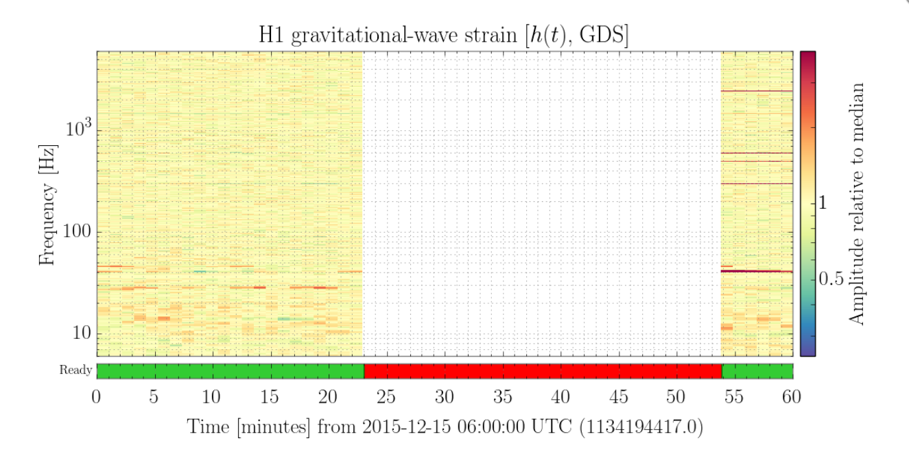
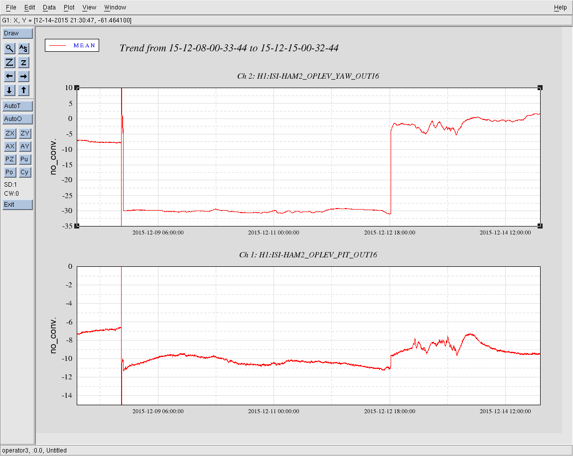
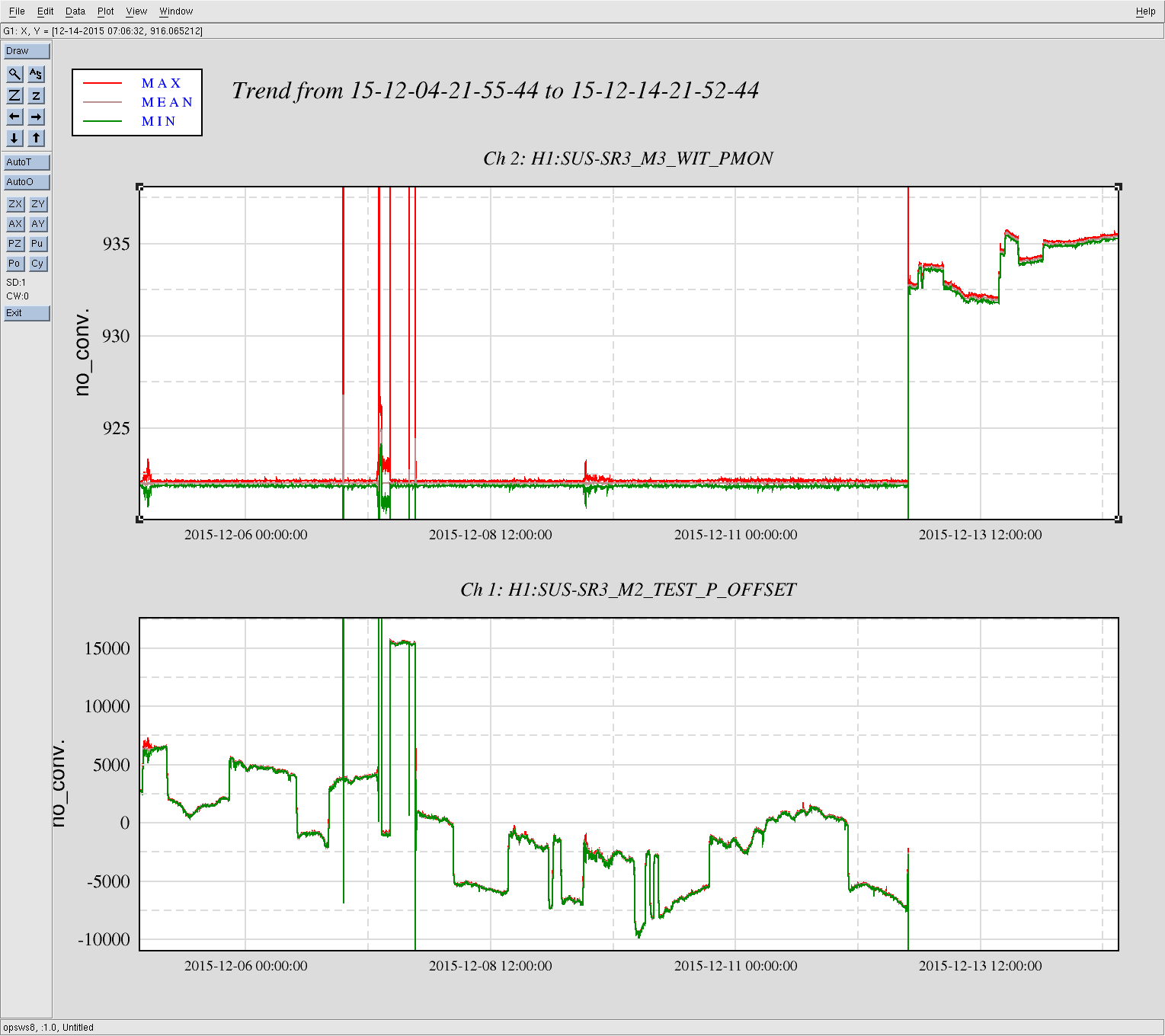
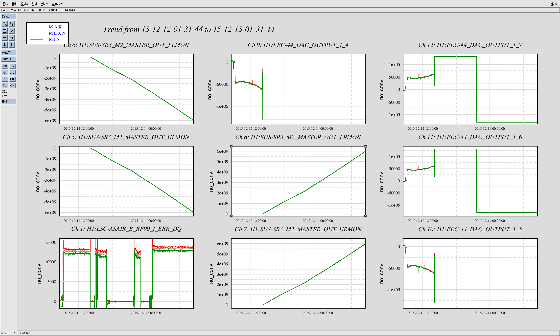
Intentionally dropped from Observing Mode to address SR3 Cage Servo, but then accidentally had a lockloss while addressing this servo. Out of Observing for roughly 3hrs. Here's timeline:
-
1:30 Dropped out of Observing to address SR3 Cage Servo, but....
-
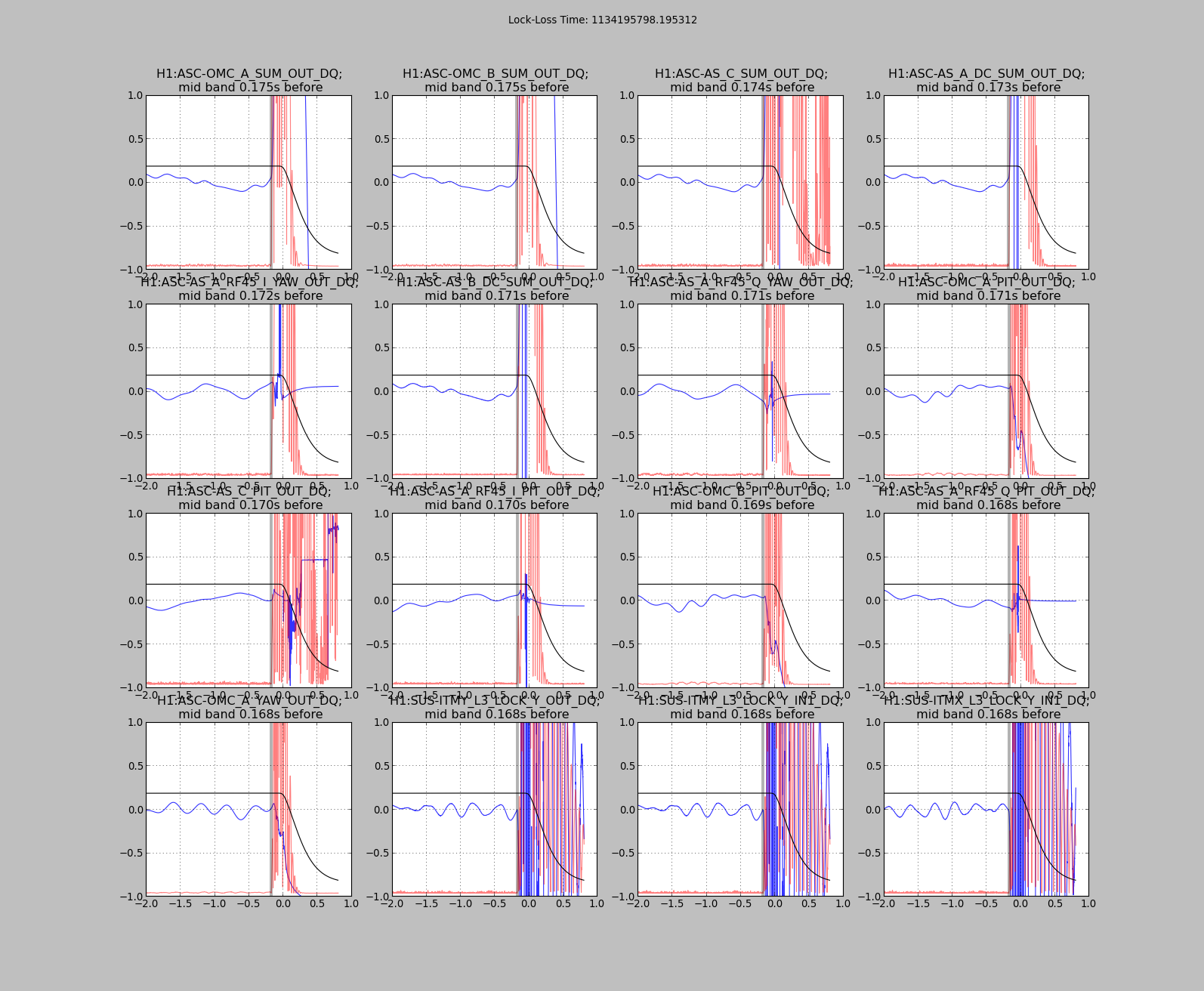
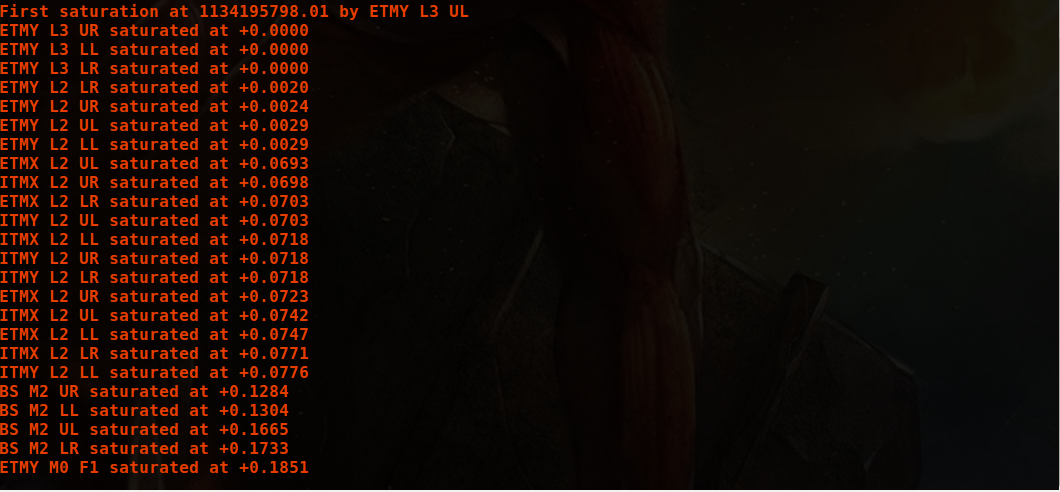
1:31 Lockloss due to SR3 Cage Servo fix
-
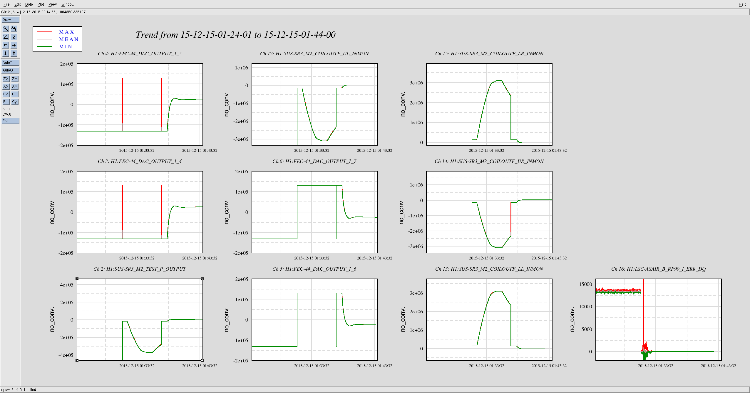
1:31 - 1:45 Fixing SR3 Cage Servo
-
1:47 - 2:36 Initial Alignment
-
2:36 - 4:21 Lock Acquisition
-
4:26 Back to Observing
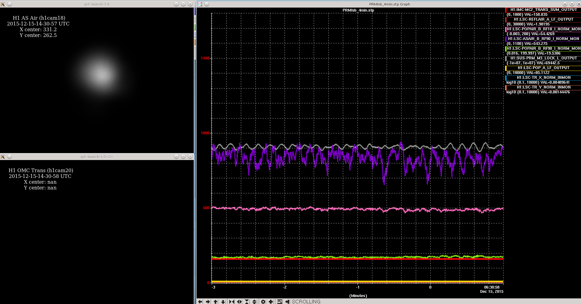
For Initial Alignment noticed the ALS arms were off in pitch and ugly, but after taking care of them, only other noticeable variance was the Dark Michelson was also off in pitch. Restored this by looking at the AS Camera and the AS_C medm window's QPD, and steering the SR2 in pitch quite a bit (from 1938 to 2022); but this is what was needed to bring the spot back down in the center of the camera. From here on, it was normal work.
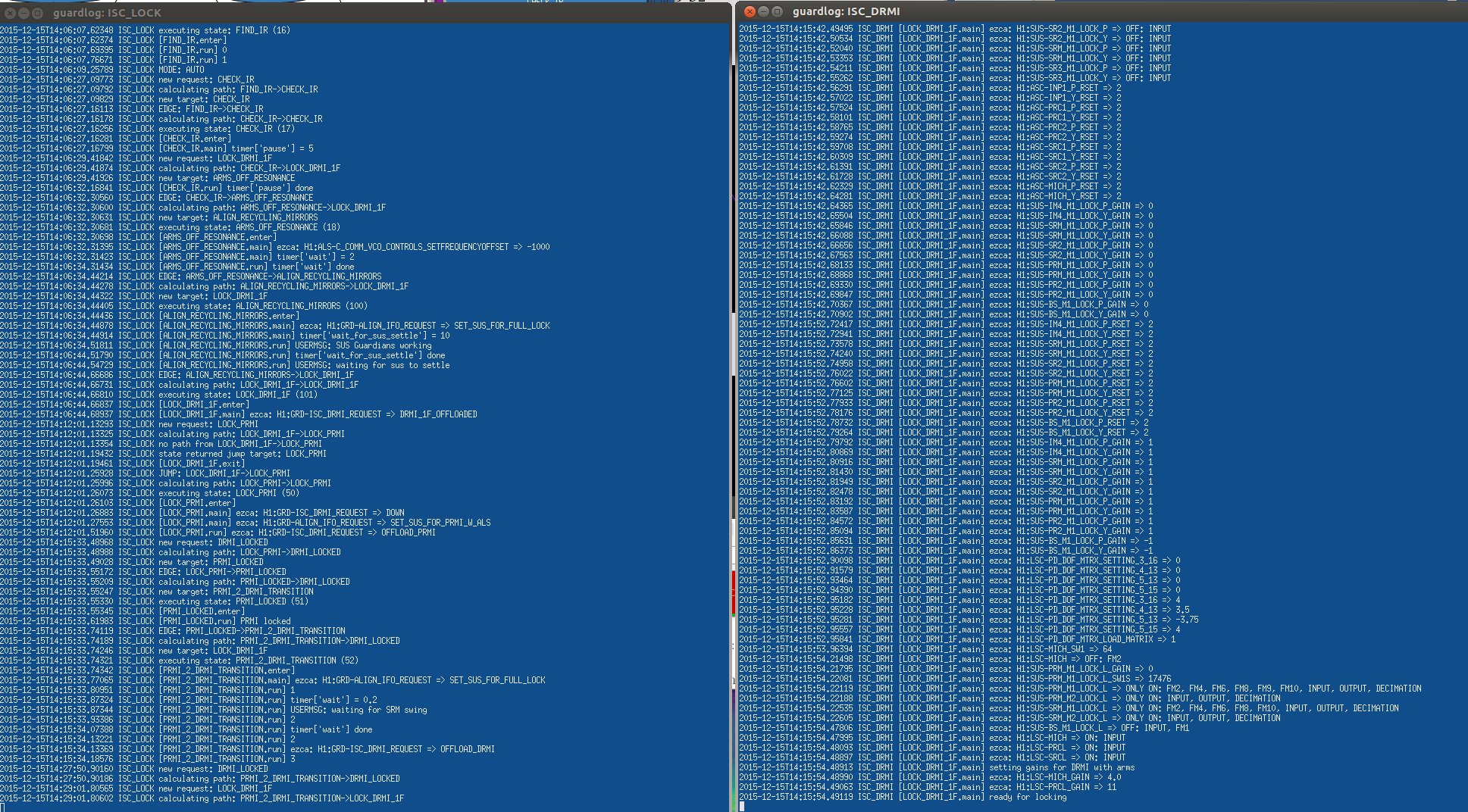
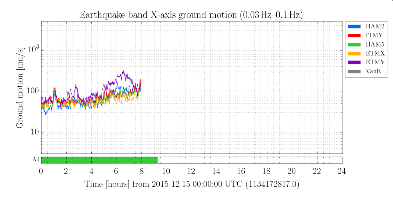
Locking was usual time sink when we have high useism (but it's dropping). During one drop, Guardian was in the middle of DC_READOUT_TRANSITION & giving OMC not locked error. I re-requested READY_FOR_HANDOFF, but H1 dropped. Think next time, we should select DC_READOUT_TRANSITION on the ISC_LOCK guardian (instead of having NOMINAL_LOW_NOISE), so that we don't fight the Guardian while locking the OMC.
At this point, we could have opted to try the new FULLY_ISOLATED state for the BS ISI, but we had been out of Observing for so long, that we decided to hold this off until Maintenance tomorrow.
H1 made it to NLN on the next lock. There were a few known SDF diffs: BS ISI time ramps (which I returned to 0sec), and the new filters Evan added for the test mases (I ACCEPTED these).
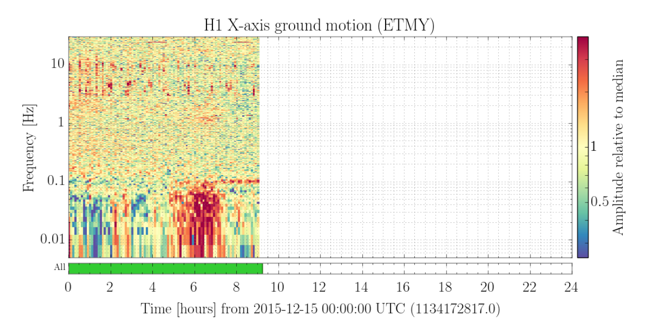
Over last 12hrs, useism has been trending down (and maybe flattening for the last 2hrs) and is at ~0.4um/s for the LVEA & winds are hovering below 10mph.