TITLE: Nov 5 DAY Shift 16:00-23:00UTC (08:00-04:00 PDT), all times posted in UTC
STATE Of H1: Observing
SUPPORT: N/A
LOCK DURATION: Entire shift
INCOMING OPERATOR: Cheryl
END-OF-SHIFT SUMMARY: IFO locked the entire shift.(currently 74.1Mpc) The winds picked up to over 20mph twice but for short periods. GraceDB Ext Not system continues its vener ending pass/fail cycle. Sei and µSei remain the same. Handing off to Cheryl.
ACTIVITY LOG:
16:30 Chris called to inform me that he would be heading out to do the aluminium stripping on the X arm
17:07 Joe out to join Chris on the Xarm
17:10 Karen into CS mechanical room to swiffer
17:15 Increase in EQ band x-axis to .1µm/s due to a pair of earthquakes around New Guinea and Timor
17:30 Winds increasing to ≤20mph
18:17 Joe back temporarily to get necessaries then heading back out. Chris is back and out to an appointment
19:57 Joe back from x-arm, for now.
21:00 X-arm crew back out to work
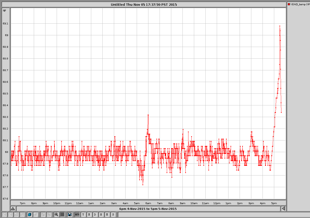
21:34 Noticed a slight downward trend in range starting about 2 hours ago. µSeism is around .3 mocrons
21:38 Kyle asked about driving forklift from shipping and recieveing area of OSB to woodshop for loading a generator to bring to X-2-8. I recommended that he doesn’t do that at this time as we are in coincidental observing mode with Livingston. I will contact him if we should break lock.
21:44 Got the OK from Landry to move the green forklift from LSB for the abovementioned task.
21:48 John W informed me that they were fixing the FMCS computer and that I was going to get some errors and alarms. ie; CS temperature is low (Nov 5 21:48:23 UTC)
22:59 Range is back up to 80Mpc
23:08 Joe reported back from X-arm. Chris will follow shortly.
23:30 Dave Barker will be going into the MSR to change tapes.