patrick.thomas@LIGO.ORG - posted 13:20, Tuesday 17 November 2015 (23476)
Ops Day Mid Shift Summary
Winds are too high to lock so maintenance is running past noon.
Winds are too high to lock so maintenance is running past noon.
I've updated tinj.m to use CAL-PINJX_TINJ* instead of CAL-INJ_TINJ*. The new changes have been implemented at LHO.

The EPICs records changed are:
  * H1:CAL-PINJX_TINJ_STATE
  * H1:CAL-PINJX_TINJ_START
  * H1:CAL-PINJX_TINJ_ENDED
  * H1:CAL-PINJX_TINJ_TYPE
  * H1:CAL-PINJX_TINJ_ENABLE
  * H1:CAL-PINJX_TINJ_PAUSE
  * H1:CAL-PINJX_TINJ_OUTCOME

To do this:
  (1) Edited tinj.m to replace CAL-INJ_TINJ* with CAL-PINJX_TINJ*. The only exception was CAL-INJ_EXTTRIG_ALERT_TIME since ext_alert.py still uses this channel and has not been switched over yet.
  (2) At 20:57 UTC turned run_tinj off with the monit web interface.
  (3) Compile run_tinj using: mcc -R -nojvm -R -nodisplay -R -singleCompThread -m run_tinj
  (4) At 21:00 UTC turned run_tinj on with the monit web interface.
  (5) Commit changes.

I checked tinj.log and it was updating as expected.

We will need to coordinate the switch-over of CAL-INJ_EXTTRIG_ALERT_TIME to CAL-PINJX_EXTTRIG_ALERT_TIME. And update LLO to this version as well.
Because Dave is finding that these are changing more frequently and thus causing him to commit more SDF snap files to the svn than he had originally planned for, I finished setting all of the SUS OPTICALIGN PIT and YAW channels (just 2 per each SUS) to not be monitored by the SDF. I also started clearing house on the new BECKHOFF SDF. In OBSERVE, this system sees more channel settings which differ from lock stretch to lock stretch. The following were set to NOT MON in SDF:
H1:*-*_*_LIMITCOUNT (Counter channelswhich have just been incrementing since the begining of the run)
H1:ALS-C_COMM_VCO_CONTROLS_SETFREQUENCY (Changes by very small amounts from lock to lock for ALS locking)
Today I re-zeroed all of the active H1 optical levers. The table below shows their pitch/yaw values before re-zeroing and the values as they read when I finished each oplev (there could be relaxation in the motors causing a slow, slight drift, especially in the BS and HAM2 oplevs which are zeroed with piezo motors steering a 2" turning mirror). This closes work permit #5606.
| Optical Lever | Old (µrad) | New (µrad) | ||
| Pitch | Yaw | Pitch | Yaw | |
| ETMx | -2.4 | -2.2 | -0.2 | 0.3 |
| ETMy | -1.3 | -6.7 | 0.1 | 0.0 |
| ITMx | -10.2 | -8.2 | -0.2 | 0.0 |
| ITMy | 7.9 | -2.6 | -0.2 | -0.0 |
| PR3 | -1.1 | -2.9 | 0.0 | 0.0 |
| SR3 | 10.1 | -5.7 | 0.0 | 0.2 |
| BS | -13.3 | -9.2 | -0.4 | 0.4 |
| HAM2 | -20.6 | -39.0 | 0.1 | -0.1 |
I reset the PSL power watchdog at 16:40 UTC (08:40 PST).
O1 day60
model restarts logged for Mon 16/Nov/2015
2015_11_16 15:46 h1sysecatc1plc1sdf
2015_11_16 15:46 h1sysecatc1plc2sdf
2015_11_16 15:48 h1sysecatc1plc3sdf
2015_11_16 15:48 h1sysecatx1plc1sdf
2015_11_16 15:48 h1sysecatx1plc2sdf
2015_11_16 15:48 h1sysecatx1plc3sdf
2015_11_16 15:48 h1sysecaty1plc1sdf
2015_11_16 15:48 h1sysecaty1plc2sdf
2015_11_16 15:48 h1sysecaty1plc3sdf
2015_11_16 15:54 h1sysecatc1plc1sdf
2015_11_16 15:56 h1sysecatc1plc2sdf
2015_11_16 15:56 h1sysecatc1plc3sdf
2015_11_16 15:56 h1sysecatx1plc1sdf
2015_11_16 15:56 h1sysecatx1plc2sdf
2015_11_16 15:57 h1sysecatx1plc3sdf
2015_11_16 15:57 h1sysecaty1plc1sdf
2015_11_16 15:57 h1sysecaty1plc2sdf
2015_11_16 15:59 h1sysecaty1plc3sdf
2015_11_16 16:06 h1sysecatc1plc2sdf
Beckhoff SDF system (running on h1build) needed a restart following problems with h1build. Note this was done in observation mode, this is a pure EPICS monitor system which access the IOC via an EPICS gateway.
At about 10:15 this morning Bubba and I disabled the fridge and the outdoor AC unit at YEND. We also concluded that the trap primers at YEND are likely mechanical only and not electrically operated.
I have completed the update and restart of the dmt software. This includes generation of segments based on ETMY-ESD DAC and DCPD ADC overflows and a few minor bug fixes. The restart also activates the calibration filter file changes made by Maddie.
TITLE: 11/17 [DAY Shift]: 16:00-24:00 UTC (08:00-16:00 PDT), all times posted in UTC
STATE Of H1: Down
OUTGOING OPERATOR: Nutsinee
QUICK SUMMARY: Start of maintenance
The h1broadcast0 daqd process has been restarted to add additional channels to the broadcast frame.
Load issues seemed to cause the server running the diskcache to freeze ast night. Now it looks like the diskcache crashed soon after I rebooted the server. I'll restart it, and the summary pages should start to update again.
Unable to maximize the ALS transmitted power just by touching ETMs and TMS alone. ITMs didn't move much compared to where it was after the lockloss. COMM beatnote is low (3ish) and touching PR3 didn't improve it.
Another 5.4M earthquake from Greece coming through...... Pause the initial alignment.
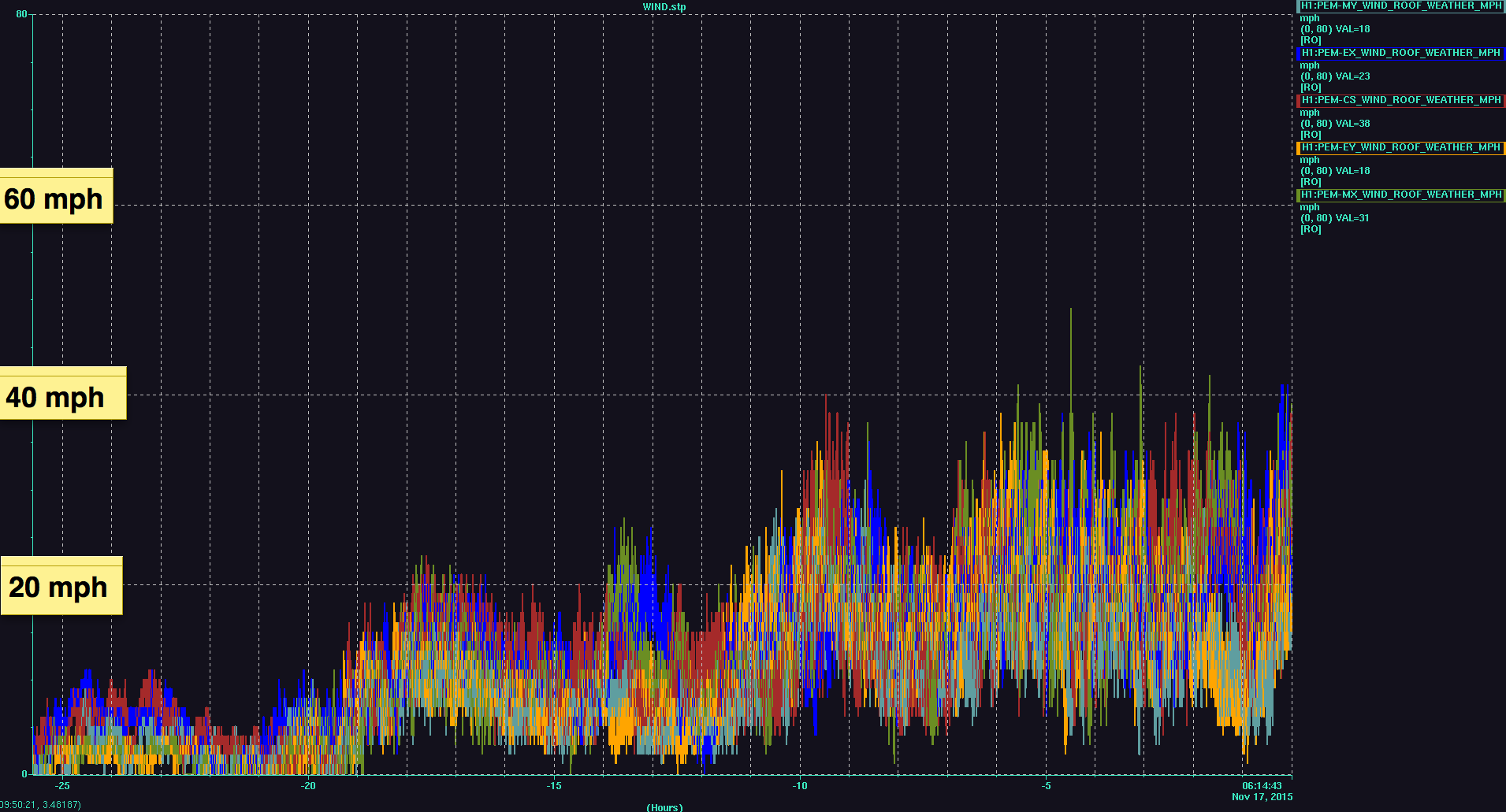
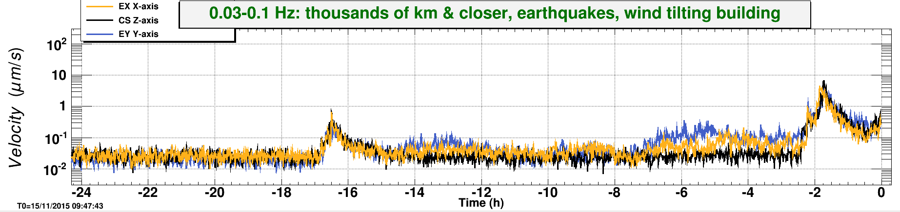
We also just had a wind gust at ~50 mph. EQ band seismic is on the rise. Relocking is going to be a while......
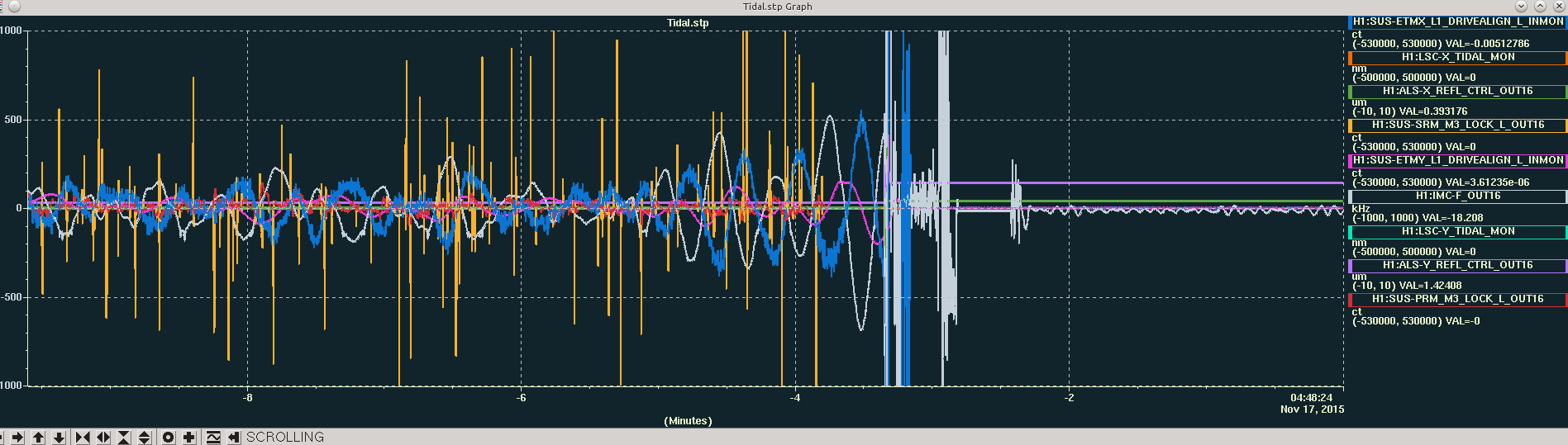
First try relocking. Lockloss at REDUCE_CARM_OFFSET (11:02:17 UTC). Wind speed ~30 mph.
Wind reaching 40 mph. Locking seems hopeless right now. Just lost lock again at CARM_ON_TR (11:08:2 UTC). Put ISC_LOCK to DOWN.
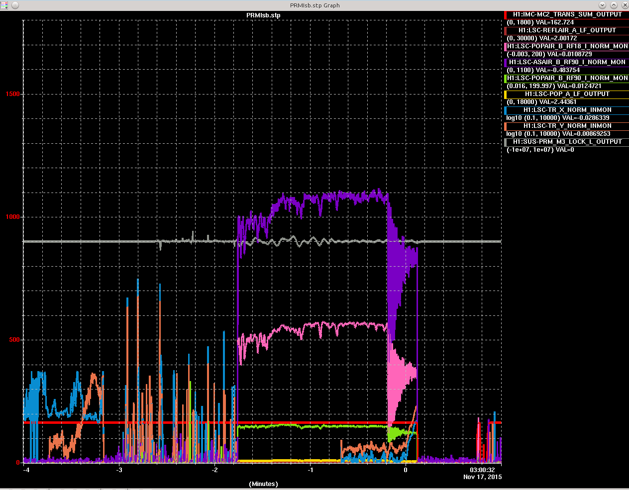
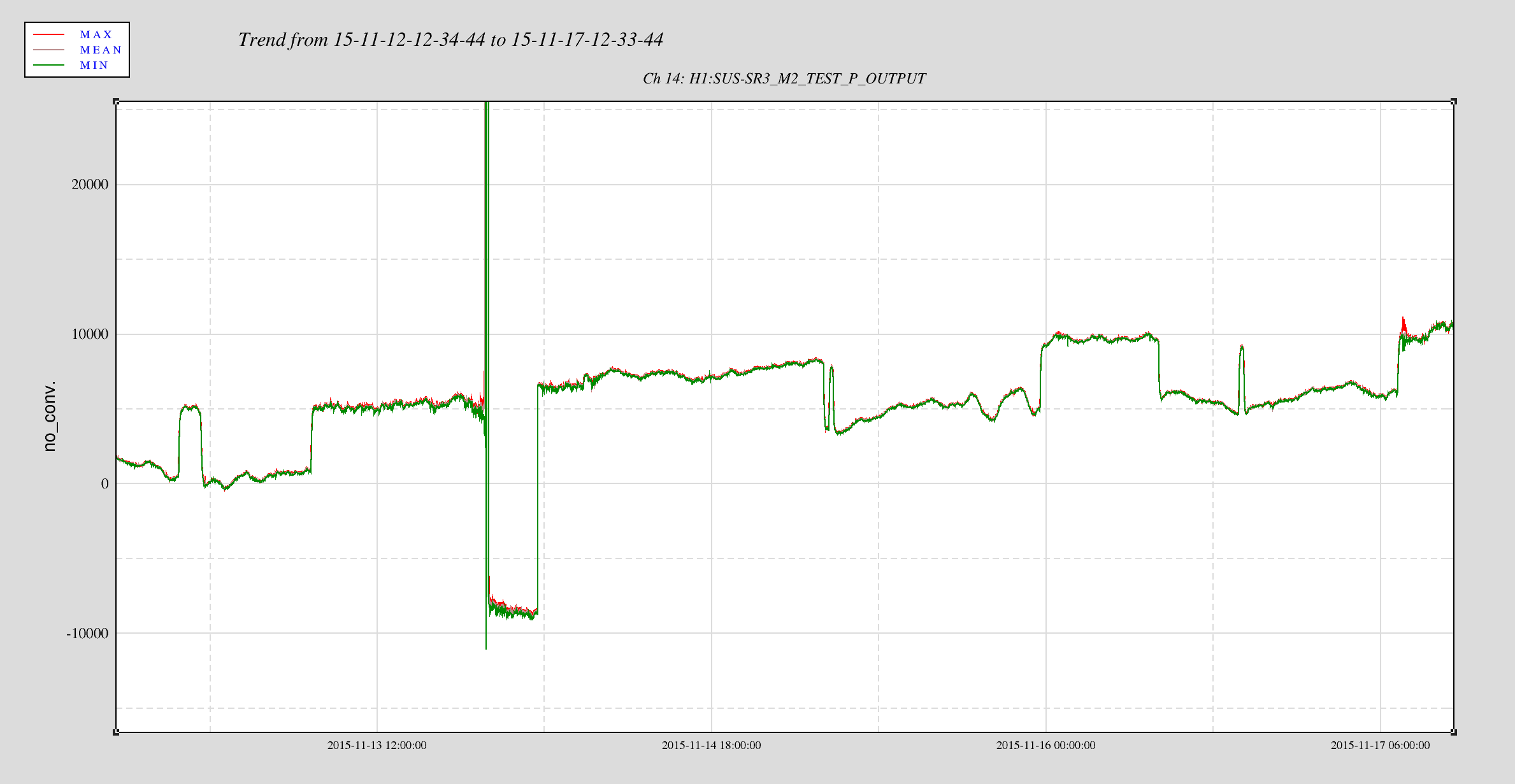
I noticed SRC_CAGE_SERVO user message tells me to "Align SR3 to offload M2 actuators". I'm not what action to take but I've attached the cage servo output below. I also noticed OMC shutter was opened while locking DRMI couple of times. Could that have intefered with DRMI locking? I don't remember the shutter being opened that early.
Tidal still high. Relocking still unsuccesful.
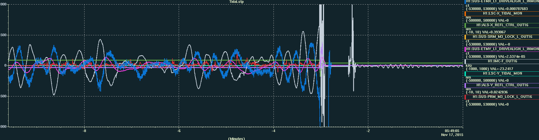
Wind speed decreased to ~20mph. So I tried again. Lockloss while locking PRMI. Looks like ETMX ran away.
Wind speed is back to ~30 mph.
The forecast lied to me saying the wind speed would decrease towards the morning. The wind has been 30-40 mph since 10 hours ago with no sign of decreasing. LLO has been down also because of wind. I'm calling it a night (or morning?).