david.barker@LIGO.ORG - posted 08:13, Friday 16 October 2015 (22583)
CDS model and DAQ restart report, Friday-Thursday 9th-15th October 2015
O-1 Days 22-28
model restarts logged for Thu 15/Oct/2015
No restarts reported
model restarts logged for Wed 14/Oct/2015
No restarts reported
model restarts logged for Tue 13/Oct/2015
2015_10_13 08:03 h1calex
2015_10_13 08:05 h1broadcast0
2015_10_13 08:05 h1dc0
2015_10_13 08:05 h1nds0
2015_10_13 08:05 h1nds1
2015_10_13 08:05 h1tw0
2015_10_13 08:05 h1tw1
Maintenance: new calex model with associated DAQ restart
model restarts logged for Mon 12/Oct/2015
No restarts reported
model restarts logged for Sun 11/Oct/2015
No restarts reported
model restarts logged for Sat 10/Oct/2015
No restarts reported
model restarts logged for Fri 09/Oct/2015
No restarts reported
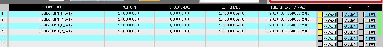


I apolgize for not reloading the guardian with the INP1+PRC1 fix.
The A2L script does not touch the loop gains at all, that is all handled by gaurdian.