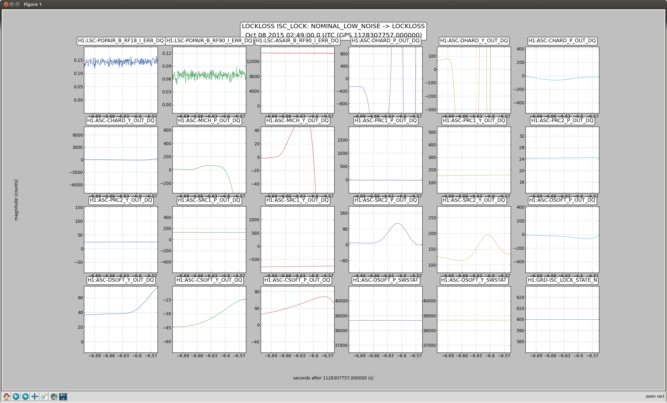
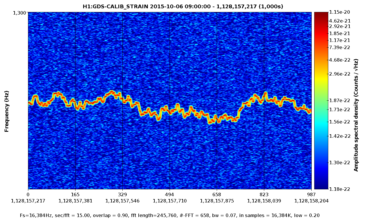
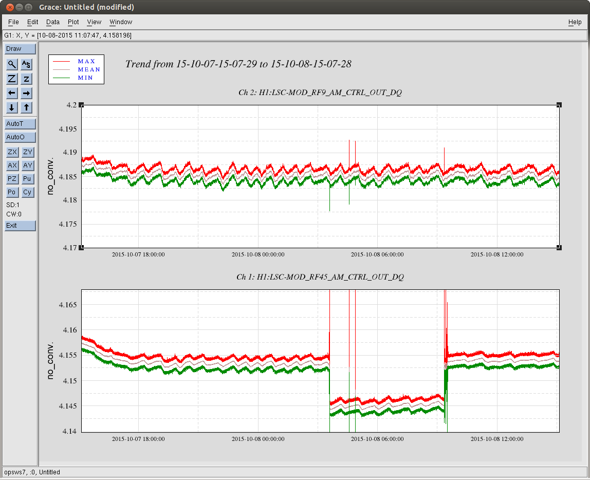
Displaying reports 65681-65700 of 83016.Go to page Start 3281 3282 3283 3284 3285 3286 3287 3288 3289 End
Reports until 12:44, Friday 10 April 2015
LHO VE
kyle.ryan@LIGO.ORG - posted 12:44, Friday 10 April 2015 - last comment - 14:00, Friday 10 April 2015(17811)
~1230 hrs. local -> Valved-in HAM6 ion pump
HAM6 being pumped by both turbo and ion pump for now
Comments related to this report
kyle.ryan@LIGO.ORG - 14:00, Friday 10 April 2015 (17815)
Ion pump controller "protect" feature shut down after 15 minutes -> Can't handle relative high pressure (3000V @ 0.05A 150W unit) -> Valved-out ion pump from HAM6 -> Restarted ion pump -> OK now
H1 SEI
hugh.radkins@LIGO.ORG - posted 10:36, Friday 10 April 2015 - last comment - 13:34, Friday 10 April 2015(17809)
WHAM6 HEPI Unlocked--Range & Linearity Test Ongoing

Preliminaries suggest some IPS could use some centering.  Currently unable to drive 0.7mm without maxing ADC (IPS side.)  More after tests complete.

Comments related to this report
hugh.radkins@LIGO.ORG - 13:34, Friday 10 April 2015 (17814)

Linearity looks good except for V1 neg.  On the Range of Motion Test, it is unable to push 0.7mm and I expect this is hitting the mechanical stop of the Actuator Plate/Bellows Shield (not adjustable.)  The only solution is to raise the platform with the big Springs.  You can see on the attached linearity plot where the V1 hits the end and skews the usual turn around.  This should not affect performance as we aren't operating out at this extreme.  Still, another for the to-do list.

Images attached to this comment
H1 DAQ (CDS)
richard.mccarthy@LIGO.ORG - posted 09:28, Friday 10 April 2015 (17807)
H1NDS1 Needed reboot
I could not connect to nds1 this morning so I contacted Dave Barker.  He tried to log in but machine was locked up.  I looked at it with the attached terminal and no obvious reason for the machine to be non responsive, but it was.  I reset the machine and everything is back. The reboot took a little longer as a check disk was done automatically because it had been 238 days since the last one.
LHO VE
kyle.ryan@LIGO.ORG - posted 09:19, Friday 10 April 2015 - last comment - 10:32, Friday 10 April 2015(17806)
Need to explain abnormal HAM6 pump curve
Current pump down much different that previous pump down of same volume (HAM6) -> Apparent gas load resulting in current HAM6 pump down curve can't be attributed to LVP Krytox grease added this last chamber entry -> Annulus volume in 10-6 torr range -> Adjacent blanked-off vent/purge and roughing pump port dead volumes were valved out after rough vacuum achieved and should still be at rough vacuum -> Need to leak test HAM6 particularly view ports and Turbo pump ballast port
Comments related to this report
kyle.ryan@LIGO.ORG - 10:32, Friday 10 April 2015 (17808)
And the "Explanation" is Graph#1 was in LOG scale and Graph#2 was in LINEAR scale (I hadn't selected this - some auto feature?) -> Aborting LD exercise
LHO General
patrick.thomas@LIGO.ORG - posted 08:47, Friday 10 April 2015 (17804)
Morning meeting notes
SEI
Unlocking HAM6 HEPI
Clean up of blend filter work from yesterday

SUS
Checks on coil driver readbacks

VAC
Pumpdown curve for HAM6 is unexpected
Opening of GV5 and GV7 is contingent upon resolution of issues with installation of beam dump on top of HAM2

FAC
Stand to anchor in DCS building
Holes to drill for stand in LVEA
Landscaping removing trees tomorrow

CDS
Filiberto working on CPS timing

PCAL
Calibration work at end X
H1 PSL (PSL)
peter.king@LIGO.ORG - posted 06:53, Friday 10 April 2015 (17798)
TTFSS Test1 and Test2 Enable
Evan and Rick reported that the Test1 and Test2 On/Off switches were always on, no matter
what the MEDM switch setting was.

The corresponding output of the AI filter checked out okay at the end of the lilac coloured
cables, for both Test1 and Test2.

The output was checked at the end of the DB37 cable going into the TTFSS.  Although a change
in voltage was observed when both switches were toggled, the change for Test2 was not high enough
to trigger the MAX333 switch inside the TTFSS.  This was traced to a problem with the HCPL2231
optocoupler on the TTFSS fieldbox (D1100367).

Since we do not currently have any HCPL2231s, part N1 and N2 were swapped since part B of N2
was not used.  This has fixed the problem for now.


Jeff B, Evan, Peter
H1 AOS (AOS, ISC, SUS)
suresh.doravari@LIGO.ORG - posted 05:56, Friday 10 April 2015 - last comment - 14:34, Friday 17 April 2015(17797)
Two Tip-tilts assembled for 40m


Two tip-tilts have been assembled for 40m.  They are sitting on the optics bench in the Optics lab.

These have thinner wire (43 microns in diameter) to avoid the hysterises seen in the thicker 125 micron wire.  Therefore these have to be handled more carefully.  The wires are quite unforgiving of any kinks or handling errors.

As agreed, these do not contain BOSEMs.  Type-B (one stage before the production line)  bosems will eventually be used in these.

The tip-tilts are ready for shipment to 40m.  They have been wrapped in Al-foil.  For long term storage, these have to be stored in a dry atmosphere to avoid rusting of the "piano wire" fibers.  The mirror holders are locked into place for shipment using the eddy current dampers on either side of the mirror mounts. 

The Sl nos are 007 and 038 (Bottom Plate).  Images of the assembled tip-tilts and their various reference numbers are attached. 

Images attached to this report
Comments related to this report
corey.gray@LIGO.ORG - 14:34, Friday 17 April 2015 (17933)

Correction:  s/n 34 will be sent to CIT (not 38).

H1 AOS (AOS, ISC, SUS)
suresh.doravari@LIGO.ORG - posted 05:36, Friday 10 April 2015 (17796)
ETMX oplev gain increased

The SUM counts on ETMX oplev laser were around 16000 counts.  I changed the Binary switch settings to increase the gain on the Whitening Chassis to bring the counts to 40k.

The new switch state of the binary switches is recorded here in the attached image.

Images attached to this report
H1 ISC
koji.arai@LIGO.ORG - posted 04:02, Friday 10 April 2015 (17782)
OMC Beacon Scan in full locking (Apr 3 data)

[Dan, Koji]

Last week, the OMC cavity was scanned with the fully locked IFO at 5.22W. In addition to the usual cavity scan analysis (let's say "DC scan"),
the technique called "beacon scan" was tried in order to check the signal content in each carrier higher-order mode.
Here are some preliimnary results.

Motivation

- Dan took OMC scans in a full lock with and without the DARM offset a while ago (LHO ALOG 16747).
- When the DARM offset is zero, basically there is no (or almost no) carrier TEM00.
- No matter how the offset is, there are carrier higher-order modes.
- This means that we are actually not sure how much of the carrier higher-order mode is coming from the arm.
- Aren't we under-estimating the signal mode matching because of the carrier that has no signal?
- We want to characterize the signal mode matching.
- We can use the DARM signal to distinguish the signal carrier and the others

Measurement conditions

- The DRFPMI was locked at 5.22W MC input.
- DARM was locked with RF with an offset. (~10mA for TEM00)
- The OMC HV PZT (PZT2) was swept from 30V to 90V with the ramp speed of 0.6V/sec (i.e. 100s per ramp).
- During the scan, the whitening filters of the DCPDs were turned off in order to prevent from their saturation.

Signal processing (Attachment 1)

- DCPD_SUM and PZT2 Readback were sampled at 16k. All the signal processing have been done offline with MATLAB.
- DCPD_SUM was preconditioned for demodulation by a bandpass with the passband of fmod +/- 20Hz, where fmod is the demodulation frequency.
- The preconditioned signal and sin or cos signals at fmod were multipled.

- The DC and demodulated signals were decimated to 512Hz (the decimation ratio=32).
- The decimation filter is the MATLAB default one. (i.e. fc=0.8*fsample, 0.05dB ripple 8th Cheby LPF)
- The decimated demodulation signals were further LPFed for noise reduction. (f_LPF = 5Hz)
- The RMS of the demodulated signals are calculated to obtain the beacon amplitude.
- The noise reduction filter imposes the phase delay in the pass band. This was approximated as a time delay.
  i.e. Negative time delay (or sample shift) of 60 samples were applied. (Dan suggested me to use "filtfilt" function
  in order to suppress this kind of phase delay. I'll use it in the future scan.)

Result (Attachment 2)

- The demodulation frequency of 1009.4Hz was used for the beacon scan.
  There was a big peak in DARM spectrum due to undamped ITM violin mode.

- As seen in the figure, a big response found at the carrier TEM00 mode. (Success!)
  (In fact, the response was too weak at the demod frequency of the calibration lines. That's the reason why the violin peak is used.)

- Not all the carrier amplitudes in the DC scan were explained by the beacon scan result.
  This indicates that each higher order modes consists of a signal carrier from the arm and a non-signal carrier.
  Note that the peaks in the DC scan and beacon scan are matched up by multiplying the factor of 5800 to the beacon result.

- As the background data, the demod frequency of 700Hz was used. There was no visible peak in the DARM spectrum at 700Hz.
  Most of the carrier peaks are above the background level. So this is not an artifact of the noise power in a peak.

Discussion

- The table below is showing the peak heights that were read from the plot. (Note this is not a peak fit result.)
  The ratios were estimated from the sum up to 8th order.

Mode       DC_scan         Beacon_scan
  #      [mA]   [ratio]      [ratio]

---------------------------------------
  0    9.18      0.589        0.928
  1    0.539     0.035        0.010
  2    0.675     0.043        0.020
  3    1.327     0.085        0.024
  4    0.564     0.036        0.004
  5    0.821     0.053        0.005
  6    1.355     0.087        0.006
  7    0.568     0.036        0.001
  8    0.559     0.036        0.001
---------------------------------------

- The table indicates that the signal mode matching was 92.8% and was way better than the DC matching.
- The 3rd and 6th order modes (both in DC and beacon) are larger than the others. Is there any reason?

How can we improve?

For better result:

- Slower scan: The cut off of the noise reduction filter is determined by the scan speed. Slower scan will improve the SNR of the measurement.
- Beacon at ETMs: The current beacon isone of the ITM violin mode. I suspect that is the reason why some of the sidebands shows some signal
above the background level. We should use pure DARM signal.
- Better alignment: The alignment of the beam to the OMC was not perfect. We can definitely improve it.

For better understanding of the result:

- Mode healing/harming: What does the SRC do for the peak heights? Are any particular modes enhanced/suppressed by the SRC?

Images attached to this report
Non-image files attached to this report
H1 SUS
stuart.aston@LIGO.ORG - posted 22:01, Thursday 09 April 2015 (17786)
SRM & SR2 (HSTS) all stages Phase 3b (in-vacuum) damped & undamped TFs for Acceptance
SRM & SR2 Phase 3b Acceptance TFs were presented in LHO aLOG entries 17633 and 17634, however, there was an issue affecting the scaling of the plots of the lower suspension stages.

The discrepancy in the scaling was as a consequence of the recent modifications to the Triple Coil Driver actuation strength carried out only at H1 (ECR E1400369) not being taken account of in the Matlab calibration script. Therefore, I've updated the Matlab (calib_hsts.m) script to support different calibrations factors for suspensions at both sites.

The aforementioned TFs have been re-processed using the updated Matlab scripts. Measurements for each stage have been compared with similar L1 and H1 Suspensions at Phase 3b (in-vacuum), as follows:-

- SRM & SR2 M1-M1 undamped & damped results (allhstss_2015-04-09_Phase3b_H1HSTSs_M1_D*_ALL_ZOOMED_TFs.pdf)
- SRM & SR2 M2-M2 undamped & damped results (allhstss_2015-04-09_Phase3b_H1HSTSs_M2_D*_ALL_ZOOMED_TFs.pdf)
- SRM & SR2 M3-M3 undamped & damped results (allhstss_2015-04-09_Phase3b_H1HSTSs_M3_D*_ALL_ZOOMED_TFs.pdf)

Summary:

M1-M1, undamped TFs are consistent with model and similar suspensions. Very minor shift of H1 SRM pitch modes above 3 Hz. Damped TFs demonstrate variation in damping between sites. However, just to note that H1 SRM vertical DOF peaks still remain relatively high Q.

M2-M2, both undamped and damped TFs taken are consistent with model and simialr suspensions. However, H1 SR2 can be seen to be weaker due to failed UL actuator (Integration Issue #930).

M3-M3, despite suffering poor coherence below 0.5 Hz, both undamped and damped TFs taken are very consistent with model and similar suspensions.

Therefore, these TFs raise no concerns for SRM & SR2 suspensions, other than the failed SR2 M2 stage actuator noted above.

All data, scripts and plots have been committed to the sus svn as of this entry.
Non-image files attached to this report
H1 SEI
jim.warner@LIGO.ORG - posted 17:55, Thursday 09 April 2015 (17790)
Consolidating BSC blend filter mods

I've been working on trying to improve BSC performance by adding elliptical filters to the CPS part of different blend filters, see logs 17702 and 17488. At ETMX I was getting good improvements in Z (first plot, black(sts) and grey (gs13) is 2 nights ago with the "old" blends, green(sts) and red(gs13) are for my new blends) so I was trying to clean up the extra filters I had (which prevent the seismic blend switching scripts from working nicely) and start exporting what I had to other chambers. This involved cutting some elements out of some existing blends and a lot of copy/paste. For example, on St1, the 90 mhz Z blend, I cut out a couple of pole and zero pairs that were very close to each other (almost cancelling each other out) and adding my ellipse. The result is shown in the second plot, blue is the stock, red is the modded version. There's a third, barely visible green trace, which is what I cut the original blend down to before adding my elliptical. I also modified a version of the 01_28 blend  from the HAMs, (third plot, blue is stock, red modded) to use in Z but ETMY keeps ringing up with this blend, so maybe I've compromised the complementarity too much. I've tried my modified blends on ETMX and ITMY and it works there. I'll get all of the chambers in a consistent configuration by tomorrow afternoon, but as of now ETMX and ITMY are in slightly different configurations from ETMY and ITMX.

Images attached to this report
H1 IOO
keita.kawabe@LIGO.ORG - posted 17:10, Thursday 09 April 2015 - last comment - 11:00, Friday 10 April 2015(17788)
Final version of parking beam dump on HAM2 didn't work (Corey, Keita)

We wanted to install the proper parking beam dump on HAM2 before we go high power, and the arm gate valves are closed right now so it seemed like a perfect opportunity. We tried, and failed.

1. Assy in question

https://dcc.ligo.org/LIGO-d1201430

It doesn't show the viewport, so it's not clear how it is supposed to be mounted, except that three hooks grab the outer edge of the flange.

2. The problem

The beam comes out of HAM2 at a steep angle (this picture was taken when we installed the non-final version back in Jan. 2014).

The new beam dump assy seems to be mounted on top of the viewport protector assy. The problem is that the protector is too high, which is kind of obvious from the above picture. For the non-final version, we had to cut the protector ring so the beam comes out of the ring, and a beam dump outside received the beam. We cannot do that with the final beam dump, and as far as the dump sits on top of the protector assy, the beam will hit the protector assy.

As of now, there is a large space between the bottom of the lexan plate and the viewport. There seems to be two versions of the protector assy, one higher than the other, and we're using the higher version. However, even if we use the lower version, it seems likely to me that the beam still does not come to the steering mirror inside the beam dump assy. It should be possible to modify the viewport protector assy such that the lexan plate sits almost flush to the viewport while the beam dump optic table sits almost fluch to the top of the lexan plate. It seems as if this works, but I'm not 100% sure without CAD.

Or maybe it is designed to be used without viewport protector assy. I couldn't find drawing that shows how it's mounted, so I'm asking around.

I told Kyle to hold off to open the gate valve in a hope that somebody offers me an easy solution by tomorrow morning.

Comments related to this report
keita.kawabe@LIGO.ORG - 19:07, Thursday 09 April 2015 (17793)

LLO people haven't installed this.

matthew.heintze@LIGO.ORG - 07:54, Friday 10 April 2015 (17800)

If I undersand what your trying to install then yes I believe it is installed at LLO. Find below some pics 

Pic 6110 is with HAM1 on LHS and HAM3 would be on RHS of pic

Pic 6114 is wth HAM 1 on RHS of pic and HAM3 would be on LHS of pic

Pic 6116 is a closer up pic of the view of Pic 6114


Ive also found in LLO 5689 some pics (see pic viewport here) with a view that gives a kind of idea on how the plate is bolted around the viewport 

Viewport porotector is not installed when this baffle used. 


The drawing for this baffle is found at D1201430. You will need e-drawing to view. It doesnt show the heat sink bolted on but I think you can work out from drawing where it goes. I believe you have screws to fasten it to viewport and also the hooks hold it to viewport (see pics), but I didnt install it personally here at LLO so going off memory


Give me a call if need be

Images attached to this comment
corey.gray@LIGO.ORG - 09:01, Friday 10 April 2015 (17803)

Apologies for late posting of photos from yesterday's fit check for the Beam Dump fixture (Porcupine Beam Dump thingie)  on HAM2's roof.  All of our work was with the Lexan Viewport Protection fixture installed (as Keita says, there are multiple versions of this fixture--basically there's a cyllinder spacer of different heights).  The current one on this viewport has a long cyllinder spacer.

Now looking at LLO's installation from Matt's sub-entry above of the porcupine beam dump, they installed this dump assembly without the Lexan Viewport Protection structure.  So right now Keita is going to contact John to see if we can install the porcupine structure without the Viewport Protection structure here at LHO. 

Below are photos from last night.  They are of only the bottom ("optic table") of the Beam dump/porcupine box---which is the part that attaches to the chamber.

  • Image 1:  This is a side shot with the Lexan fixture in place and one of the "hooked screws" dangling off the Beam Dump Bottom (screw is intentionally upside down, we just wanted to  see if this thing could hook under the viewport--it obviously is not even close!
  • Image 2:  This photo shows the Bottom Optics Table of the Beam Dump, but under it, one can see the Lexan Protection Cover.  The part of this cover which was cut to catch the shallow beam coming out of HAM2 is circled in red.

  • Image 3:  This photo shows the specific path the beam has to make it out of HAM2.  There is a baffle inside HAM2 which has a hole in it for the exiting beam (circled in green).  So with that hole and then where the cut out is in the Lexan Protection Cover part, one can see the shallow angle-ed beam we want to catch coming out from HAM2.

Images attached to this comment
dennis.coyne@LIGO.ORG - 11:00, Friday 10 April 2015 (17810)

There was a question raised about whether this viewport (on port D8 of HAM2; see D980226 for HAM chamber port designations) is a double-window version.The viewport window assembly number is D1101670. The viewport source list (T1100292), the L1 viewport survey (E1200445), and the 3rd IFO viewport inventory (T1500105) all indicate that the viewport assembly that should be installed on port D8 of HAM2 is a double-window version (D1101670). Unfortunately we could not find an H1 viewport survey in the DCC, but Gerardo reported that this viewport is a double-window version.

H1 SUS
betsy.weaver@LIGO.ORG - posted 15:59, Thursday 09 April 2015 - last comment - 07:50, Friday 10 April 2015(17779)
PR3 M3 Acceptance TFs

I found damped TFs which Kissel took last Dec when he imported the LLO HLTS filters and applied them to the LHO HLTSes 15730.  Today, I ran the undamped set.  Attached are results and comparisons with other HLTSes.  I think this closes the PR3 acceptance measurement dedt.

Non-image files attached to this report
Comments related to this report
stuart.aston@LIGO.ORG - 07:50, Friday 10 April 2015 (17801)
Thanks for processing and posting. All looks good, I have no concerns!
H1 PSL (ISC, PSL)
evan.hall@LIGO.ORG - posted 00:31, Thursday 09 April 2015 - last comment - 15:39, Thursday 03 December 2015(17766)
Another 3 dB of FSS gain

Rick, Evan

Summary

This evening we went into the PSL and examined OLTF of the FSS.

Since we want to increase the FSS gain, but cannot turn the common gain slider up any further, we looked for other ways to squeeze more gain out of the loop.

Rick had the idea to try to increase the error signal slope by adjusting the demod phase using the delay line. Indeed, we were able to increase the loop gain uniformly by 3 dB. The phase remained more or less unchanged below 700 kHz.

We now have a UGF of about 350 kHz with 50° of phase. The gain margin is about 3 dB.

Details

Delay line switch positions (up/down) are as follows:

Delay (ns) Old New
1/16 D D
1/8 D U
1/4 D U
1/2 D U
1 D U
2 D U
4 D U
8 U D
16 U U
1/16 D D
1/8 D D
1/4 D D
1/2 D D
1 U D
2 U D
4 U D
8 D D
16 D D
Total 32.9 ns 40.0 ns

So the phase change at 21.5 MHz is 56°. That seems like quite a lot, so perhaps we should take a closer look at the error signal with the FSS unlocked to make sure it's reasonable.

Also, on the manual FSS MEDM screen, we found that the TEST2 enable/disable button didn't really work; we seemed to get a sensible transfer function no matter what.

Non-image files attached to this report
Comments related to this report
evan.hall@LIGO.ORG - 10:47, Friday 10 April 2015 (17792)

Peter K, Jeff B, Evan H

We did some FSS diagnostics today in and around the PSL:

  • We measured the LO going into the FSS tabletop box; it is 20.0 dBm.
  • We also measured the refcav powers: with 28.3 mW incident, we have 11.8 mW transmitted immediately after the refcav. The transmission PD voltage was 1.15 V. But I think this must have been during the time at which the ISS AOM was diffracting an anomalously high amount of power, since the best transmission PD voltage we've observed is more like 1.5 V.
  • By driving the NPRO PZT with a triangle wave, we took sweeps of the error signal, the cavity transmission, and the cavity reflection.
  • We were able to entirely remove the delay line phase shifter. We replaced it with about 20 cm of extra RG58.
  • For a stable lock with a >300 kHz UGF, we had to adjust the common (PZT+EOM) and fast (PZT) gains to 26 dB and 21 dB, respectively (they were 30 dB and 15 dB) before. As we were leaving we noticed the loop started to oscillate, so we backed off the common gain to 24 dB instead.

Originally there was 14.5 dBm of 21.5 MHz drive going into the delay line, and 8.1 dBm coming out (and thus going to the EOM). So we have won back almost 6 dB of drive to the EOM. That's roughly consisent with the extra headroom we now have on the common gain slider.

However, I do not understand why we had to adjust the fast gain after removing the delay line. With 26 dB common and 15 dB fast, we saw a broad peak in the transfer function around 50 kHz or so, and we increased the fast gain to 21 dB to suppress it. So perhaps removing the delay line shifted the crossover frequency.

A new OLTF is attached (at 26 dB of common gain), along with the error signal and cavity sweeps that we took (which are now outdated).

Non-image files attached to this comment
evan.hall@LIGO.ORG - 15:39, Thursday 03 December 2015 (23910)

Using data (scope_7.csv) in the above attachment, we find that the PSL NPRO PZT actuation coefficient is 1.3 MHz/V [ = 21.5 MHz / (7.11 V + 9.09 V)].

H1 SUS
betsy.weaver@LIGO.ORG - posted 11:25, Thursday 02 April 2015 - last comment - 22:06, Thursday 09 April 2015(17634)
SR2 Acceptance TFs

Attached are the Phase 3b damped and undamped TFs of SR2 taken over the last few months.

Note, there is only the damped M2 stage TF due to the fact that there is a broken coil o magne at that stage and I was leary of driving too hard or too much.

Non-image files attached to this report
Comments related to this report
stuart.aston@LIGO.ORG - 22:06, Thursday 09 April 2015 (17795)
Due to a scaling issue affecting lower stages of the suspension, these TFs have been re-processed, and are presented in LHO aLOG entry 17786.
H1 SUS
betsy.weaver@LIGO.ORG - posted 11:22, Thursday 02 April 2015 - last comment - 07:42, Friday 10 April 2015(17633)
SRM Acceptance TFs

Attached are the Phase 3b damped and undamped TFs of SRM taken over the last few months.

Non-image files attached to this report
Comments related to this report
stuart.aston@LIGO.ORG - 07:42, Friday 10 April 2015 (17799)
Due to a scaling issue affecting lower stages of the suspension, these TFs have been re-processed, and are presented in LHO aLOG entry 17786.
Displaying reports 65681-65700 of 83016.Go to page Start 3281 3282 3283 3284 3285 3286 3287 3288 3289 End