cheryl.vorvick@LIGO.ORG - posted 12:44, Thursday 29 October 2015 (22956)
IM2 alignment shifts - four times in 7 days
I've tracked the alignment shifts in IM2 over 7 days, and it's shifted four times.
The largest shifts for IM2 are in pitch:
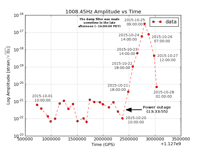
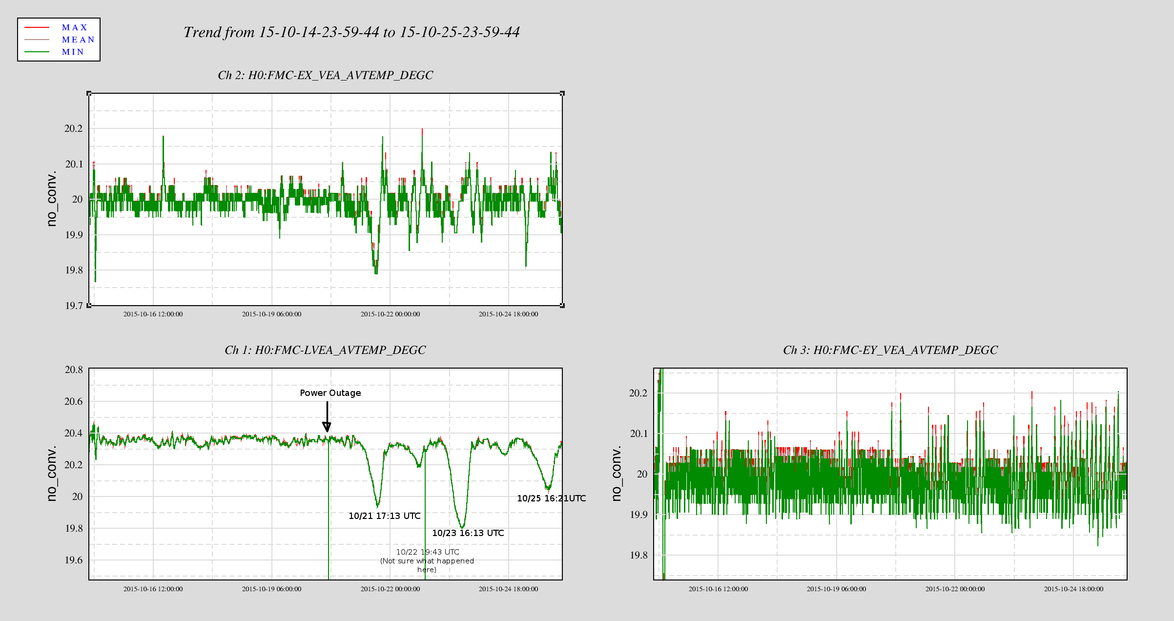
- +71urad, power outage, 20 Oct
- -41urad, shaking/possible ISI trip, 20 Oct
- +48urad, earthquake with ISI trip, 26 Oct
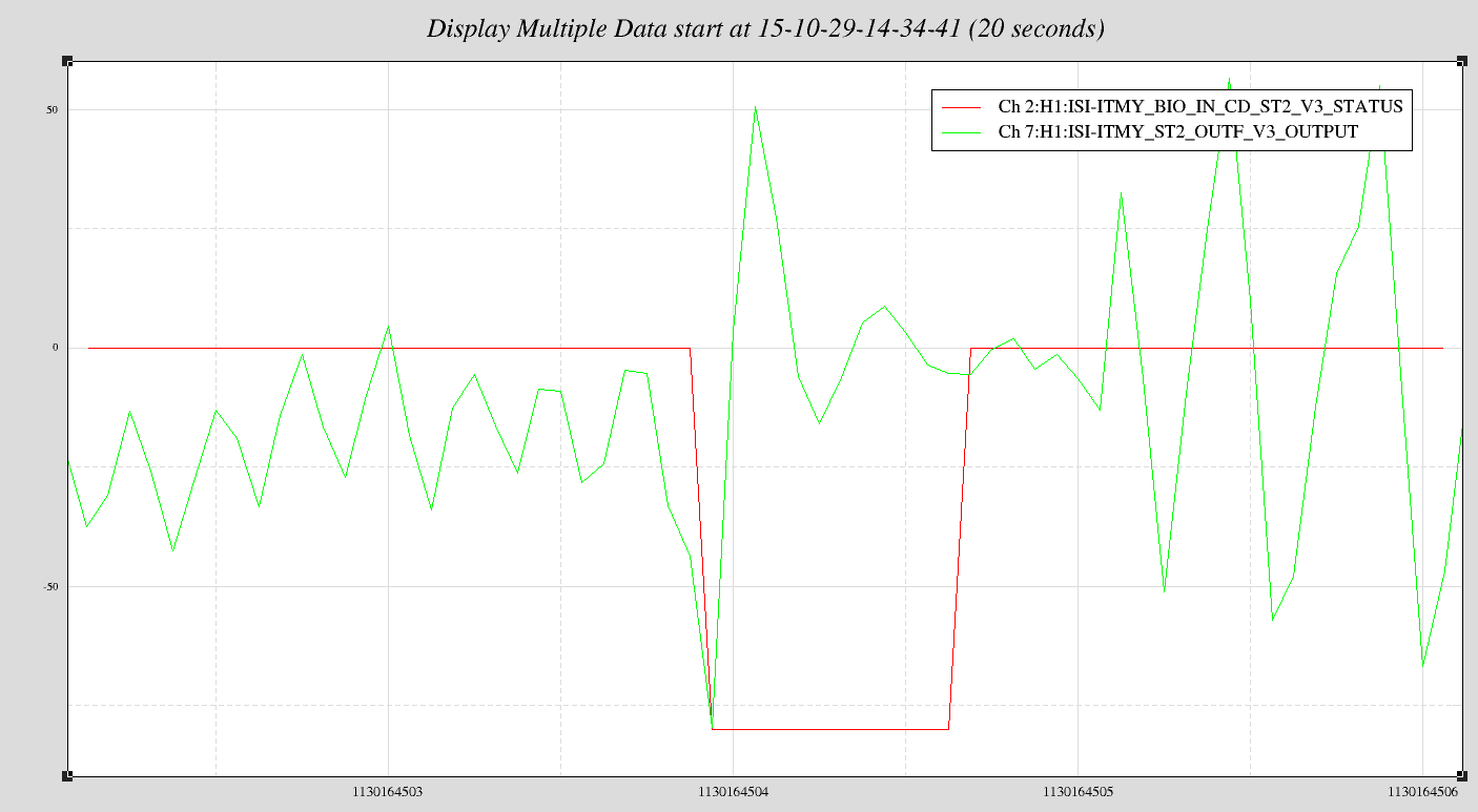
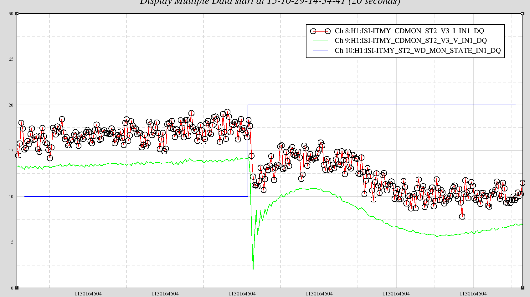
- -40urad, ISI trip, 27 Oct
The other IMs are also shifting, and I haven't looked at every event for all IMs, but for the power outage event, IM2 pitch was the largest shift at +71urad, IM1 and IM3 both had shifts in pitch of about -20urad, PRM yaw shifted -9urad, and all other HAM2 optics (IM4, MC1, MC3, PR3) pitch and yaw have shifts of 5urad or less.
The only possible conclusion is that IM2 has a problem, and likely also IM1 and IM3 have the same problem but to a lesser degree.
Non-image files attached to this report