nutsinee.kijbunchoo@LIGO.ORG - posted 08:11, Tuesday 27 October 2015 (22876)
LVEA is LASER SAFE
Richard has transitioned LVEA to laser safe. All doors are locked. PSL still up. IMC still locked.
Richard has transitioned LVEA to laser safe. All doors are locked. PSL still up. IMC still locked.
TITLE: Oct 27 OWL Shift 7:00-15:00UTC (00:00-08:00 PDT), all times posted in UTC
STATE Of H1: Maintenance
SUPPORT: Jenne, Kiwamu
LOCK DURATION: ~6.5hours
INCOMING OPERATOR: Nutsinee
END-OF-SHIFT SUMMARY: IFO is locked and observing for ~6.5hours @ ~ 80Mpc. EQ sei bands are ~.22 microns/s. µSei is still a bit elevated to about .4 microns/s. Wind is calm.
SUS E_T_M_Y saturating (Oct 27 10:49:18 UTC)
SUS E_T_M_Y saturating (Oct 27 14:02:30 UTC)
SUS E_T_M_Y saturating (Oct 27 14:18:15 UTC)
ACTIVITY LOG:
07:17 Kiwamu on site to do some magic
07:30 Kiwamu manually engaging ISS second Loop
07:51 Observing mode
08:01 Lockloss
09:25 H1 back into Observing mode after much tweaking of IMs.
09:40 Oscillation in DHARD appeared in the ASC signals. Kiwamu lowered the gain to this loop to save the lock. (Commissioning Mode)
09:53 H1 back to Observing
11:13 Kiwamu is done and leaving the site.
12:04 restarted GraceDB script again
14:18 Chris, Joe and Bubba staging materials for grouting activities
14:34 Jeff is going to be taking a trailer around the side of the building and staging the forklift for work with Jody.
14:40 Richard out to LVEA to transition to LASER SAFE
15:00 Sprague on site
MID-SHIFT SUMMARY: Kiwamu has managed to correct some alignment offsets which occurred in the IMs during yesterday’s earthquake recovery. These alignment corrections along with some ASC gain adjustments seem to have removed the oscillations that were occurring. There was also some difficulty with engaging the ISS Second Loop. It had to be done manually during each locking sequence. It is my understanding that the ISS issues are previously scheduled to be addressed during normal weekly maintenance. the IFO is locked and observing for just a little over an hour now at ~ 80Mpc. EQ sei bands are ~.22 microns/s. µSei is still a bit elevated to about .5 microns/s. Wind is calm. I had to reset the GraceDB External Alarm Notification script. Livingston appeared on the BNS range graph about 15 minutes ago
Ed, Patrcik, Kiwamu,
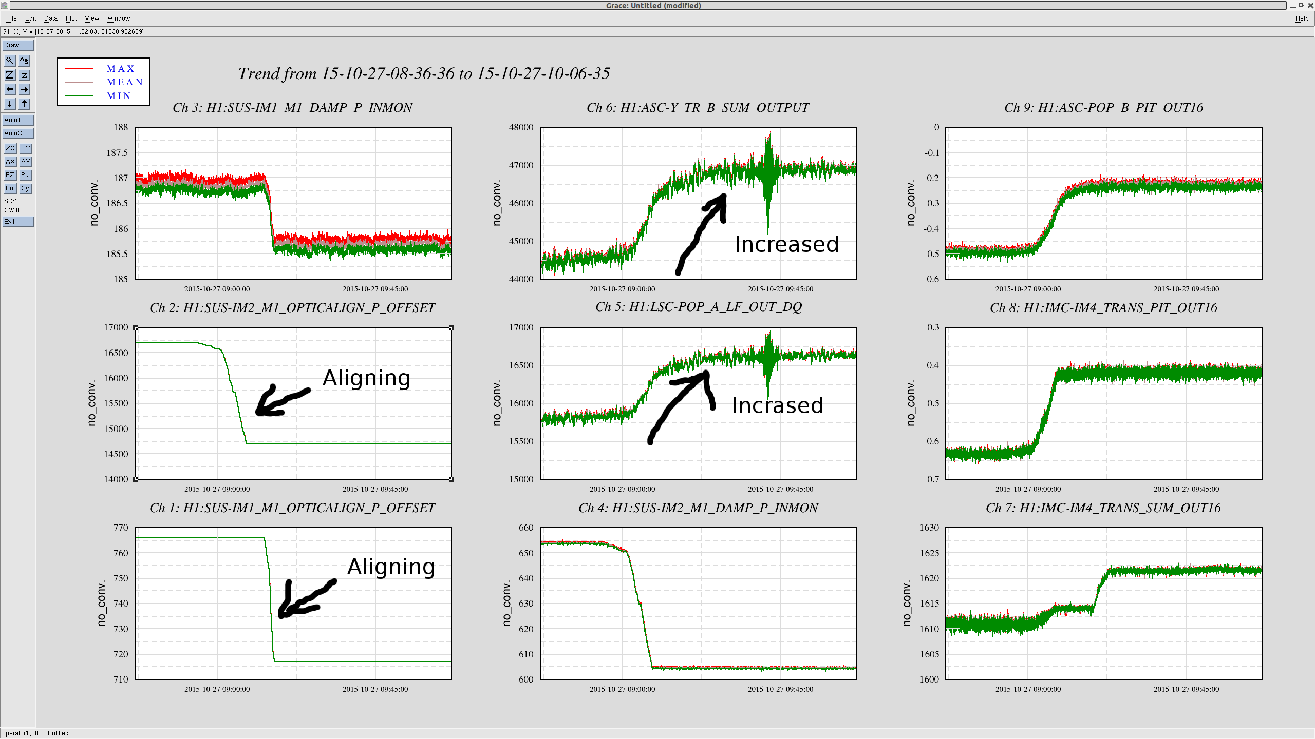
In addition to the ISS issue (alog 22863), tonight we had two other issues with the alignment loops (DHARD instability and SRC2 instability, reported in alog 22859). After some investigation, we found that IM1 and IM2 had different alignment than usual, mainly in pitch. Even though we are not sure how exactly this affected all three issues we had tonight, we realigned them so that the OSEMs read the same values as the past. This resulted in two positive consequences as follows.
(1) Realigning IM1 and IM2 brought IM4 trans and POP_B QPDs back to where they were.
(2) The realignment increased the carrier power in both PRC and arm cavities by 5 or 6 %.
See the first attachment for the increased carrier power. We aligned IM1 and 2 while the interferometer was locked at low noise. We accepted the new IM alignments in SDF (see the third attachment). Even though we still suffer by the DHARD instability, at least the SRC2 instability seems to have gone away after the realignment. I did not attempt to maximize the carrier power but it makes me think that there might be a "sweep spot" for IMs' alignment where the carrier power is maximized in the interferometer. Also, note that IM4 trans sum increased as well with the newly aligned IMs, but only 0.6% perhaps due to the beam on IM4 trans getting centered.
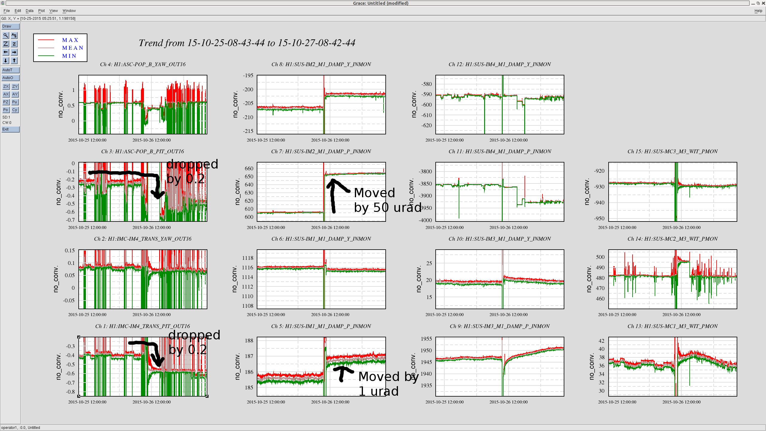
IM1 and IM2 moved likely due to the untrip of HAM2
According to trends, it seems that both IM1 and 2 changed the alignment at the time when Ed untripped HAMs 2 and 3 (alog 22835). This effect is something we already knew (alog 22719). For some reason, this time it changed mostly IM1 and IM2 in pitch. See the second attachment for the trend. IM1 moved by about 1 urad, and IM2 moved by about 50 urad as seen by the OSEMs. Also, yaw of IM1 and 2 also moved, but neither IM4 trans nor POP_B see a significant change in yaw. The MC mirrors seems to have been unchanged.
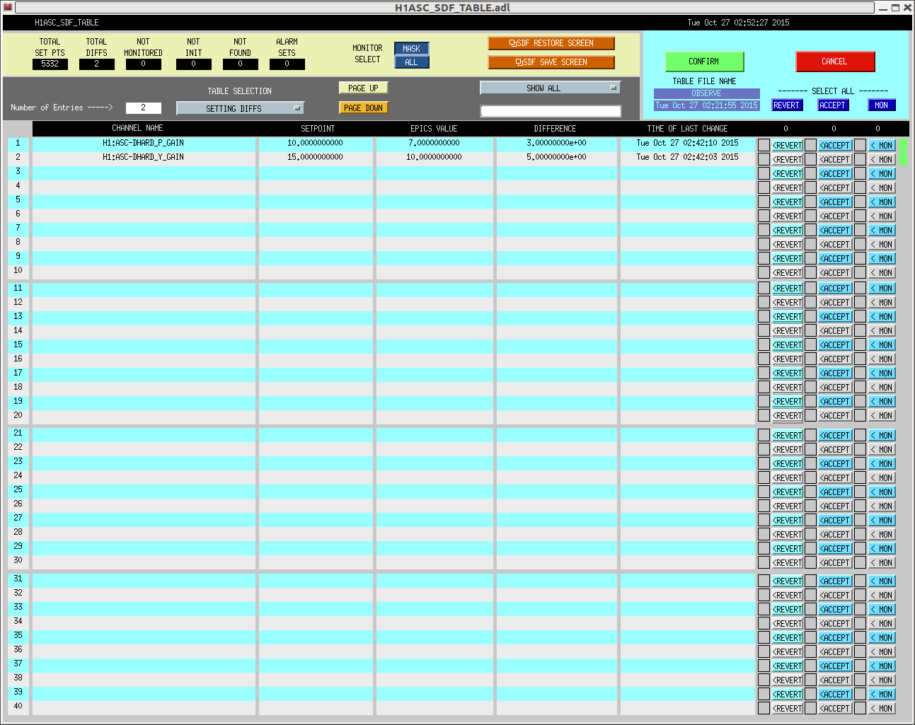
DHARD is still unstable
I was hoping that the realignment of IMs would magically fix all the issues we had, but the DHARD instability seems to remain. The symptom is that both pitch and yaw DHARD oscillate at around 0.6 Hz. As was suggested by Jenne, we decreased their loop gain which fixed the instability. I have no idea why they oscillate at 0.6 Hz and why the gain reduction helped. The pit gain is set to 7 (which was 10 originally), and the yaw gain is set to 10 (was 15 originally). For this lock stretch, we accepted these values in SDF and this means that they will show up in the SDF next time when we lock the interferometer. See the fourth attachment for the SDF.
To those who will relock next time
Since we have aligned IM1 and IM2 in situ when the interferometer was locked at low noise, the interferometer alignment in the cold state will be somewhat far from the optimum. I would recommend running the full initial alignment before relocking.

10:35UTC
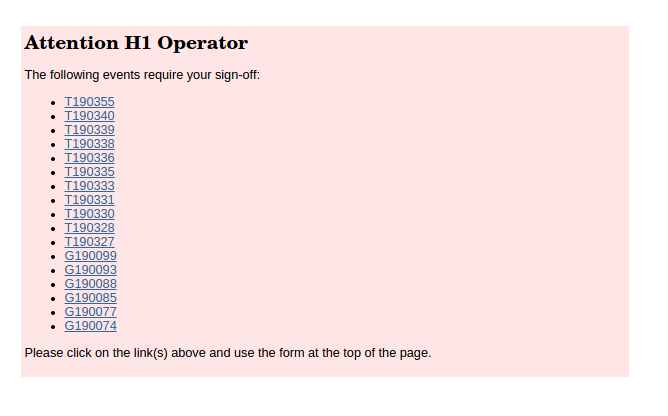
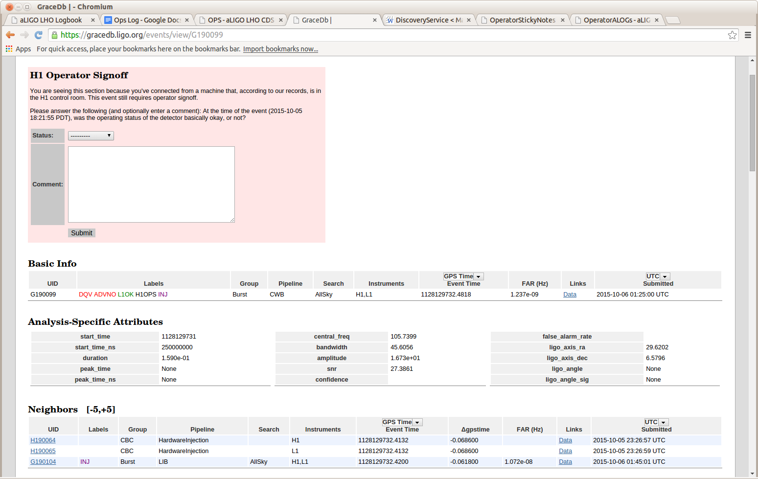
These all appear to be test injections that occured between Oct 5-6. I looked at the page out of curiosity and I saw this list on the home tab. I'll defer attention to these to someone who was involved in those activities.
09:25UTC
~09:40UTC Oscillation in DHARD appeared in the ASC signals. Kiwamu lowered the gain to this loop to save the lock. (Commissioning Mode)
07:51UTC
Growing hf oscillations visible in POP18 and MC2 Trans eventually caused SR2 saturation and lockloss. Kiwamu still here working on it.
TITLE: Oct 27 OWL Shift 7:00-15:00UTC (00:00-08:00 PDT), all times posted in UTC
STATE Of H1: Locking
OUTGOING OPERATOR: Patrick
QUICK SUMMARY: Jenne and Patrick discussing the state of affairs with Doug at Livingston. They’ve been down for 30+ hours and we’re currently having issues with ISS second loop not engaging. Kiwamu is on his way in. It looks as if my shift will get cut short when L1 goes into maintenance day (04:00PDT)
Yet again, we had trouble with engaging the ISS.
I put in a notification during ENGAGE_ASC_PART3 for the operator to check the diffracted power level if it is more than 0.8% away from nominal. While it's probably okay if it's within 1% (other alogs say 2%, but I've had more consistent success with 1%), I chose a somewhat smaller number out of an abundance of caution.
However, even though the diffracted power was within a few tenths of a percent of nominal, the ISS would stall, and not engage.
As part of the PREPARE_ISS state, the guardian changes some setpoint values such that the H1:PSL-ISS_SECONDLOOP_SIGNAL_OUTPUT channel becomes small. We need to do this so that the DC-coupled ISS doesn't kick us out of lock when it is engaged. (For unknown reasons, this convergence has seemed to be more successful when the diffracted power is close to 8%). This SECONDLOOP_SIGNAL_OUTPUT wasn't converging though. It was bouncing around between +/-5 counts. The absolute value of this channel must stay below 2.5 counts in order for the ISS to close the second loop.
In the end, what I did, was cheat and change the gain H1:PSL-ISS_SECONDLOOP_SIGNAL_GAIN to 0.1 so that the ISS second loop would turn on. Then, VERY slowly I turned the gain back after we had arrived at NomLowNoise. As I increased the gain in steps of 0.1, the diffracted power dropped by half a percent or so. So, at each step, I waited for the diffracted power to come back near 7% or so before going to the next step. While this worked once, it has failed a few times after that, so let's not make it the new plan.
Patrick and I called Kiwamu, and followed the instructions in aLog 22449 to manually turn on the second loop (basically, turn on the button next to "second loop input to first loop" on the second loop screen, when the second loop output (near bottom right of that screen) is close to zero). Anyhow, that is making the diffracted power go super low (less than 1% sometimes), until the outer loop loses lock, and the diffracted power jumps up really high (45% or more). At this point, it's not at all clear why this isn't working, so Kiwamu is on his way in to try to diagnose things.
We've checked in with Mike, and since LLO is still down, if Kiwamu and Ed can't figure out the ISS, we'll call off the rest of the owl shift.
As Jenne reported, the second loop output signal did not converge with the software PID loop tonight for some reason. Another bad thing was that the manual engagement (alog 2249) for some reason tended to pull the diffraction power to a very low value, which eventually broke both the 1st and 2nd loops and made a big bounce in the diffracted power which reached about 40%. After I arrived at the site, this issue of the 2nd loop pulling the diffraction power downwards did not happen. I could not determine what went wrong. We will test this issue during the maintenance period today.
In order to identify what parts keep failing, I paused the IMC_LOCK guardian and engaged the 2nd loop step by step manually. In the end, I did not see any failure behavior at all. So I could not determine what parts were bad in the sequence of the engagement. Since we lost lock another time, I tried the manual engagement again following my instruction in alog 2249 without pausing the guardian. This also worked fine. I am baffled. The only consistent behavior is the PID loop which does not converge.
TITLE: 10/26 [EVE Shift]: 23:00-07:00 UTC (16:00-00:00 PDT), all times posted in UTC
STATE Of H1: Lock acquisition
SHIFT SUMMARY: Initially had trouble locking DRMI. Went to LOCK_PRMI and aligned the BS. Jenne had put the ISI blends back to 45 mHz. Could this have moved the BS alignment? Successfully moved from LOCK_PRMI to LOCK_DRMI. No trouble locking DRMI since. Evan, Jenne and Sheila worked on ASC SOFT loop instability (see alog 22858). We made it to nominal low noise but loss lock while running the a2l script (see alog 22860). Second lock at nominal low noise was lost after trouble with the ISS second loop.

Still having trouble with ASC loops and also with the ISS second loop. Jenne and I called Kiwamu about the ISS second loop and he decided he will drive in. Also contacted Mike. We have permission to call off the second half of the owl shift if no progress is made.
INCOMING OPERATOR: Ed

03:58 UTC GRB alert. Neither IFO locked.
04:21 UTC Locked at NLN. Set H1:SUS-ETMY_L2_DAMP_MODE3_GAIN to 10 and H1:SUS-ETMY_L2_DAMP_MODE9_GAIN to 200 as per SDF differences.
05:04 UTC Lock loss.
05:13 UTC ISI EMTY Stage 2 WD tripped after locking on DRMI 1F. Jenne reset it.
05:39 UTC Locked at NLN.
05:41 UTC Lock loss. Trouble with ISS second loop.
It may have gotten lost in all of the alogs over the weekend, but I mentioned in a comment to an old alog (22789) that we had not been getting any real data for the ETMY spot positions.
Since LLO is still down, and I've been here all day trying to get the IFO locked, I rewarded myself with ~15 minutes of A2L investigation.
It turns out that we have had the input to the ETMY L2 DITHER filter bank off, so we weren't actually dithering ETMY. So, that explains why all of the data we have been getting looked so poor. Anyhow, I have turned those on and accepted them in SDF, so when the oscillators turn on with the a2l script, we should actually be sending some signal out.
Evan and Sheila have left. Jenne is still here. We have made progress but the ASC loops may still be unstable (but in a different way than before). The wind has come down below 10 mph. The microseism is between .2 and .5 um/s.
We had one lockloss that was due to a DHARD oscillation. I didn't change anything, and the next lock was successful.
We finally got to NomLowNoise, and about an hour after Engage ASC, SRC2 Pitch started oscillating. I was running a2l, but that hopefully didn't cause the problem. In the past, we hadn't actually been dithering ETMY, but I found why that was, so this run of a2l was the first that had dither lines going to all test masses simultaneously, so it's possible that that was too much for the IFO to handle.
Patrick, Jenne, Sheila, Evan
When the wind died down and we were able to relock using 45mHz blends, we decided to have a quick look to see if we can fix the problems we've been having with soft loops. In the end we just made the low gain that we have been using with the soft loops when we are using 45mHz blends permanent.
Background: some gain peaking in the soft loops unfortunately seems to be at the same frequency as the gain peaking in the 45mHZ blends, making it dangerous to turn the soft loops up to their full gain when we are on the 45mHz blends because of the microseism. The operators have been manualy turning down the gain in these loops in the last week when they are using 45mHz blends.
We wanted to try to fix the instability in these loops but didn't suceed. Along the way we noticed that we have 20dB more gain in the offloading path for the ITMs than the ETMs. In the words of Daniel sigg, this is the underbrush of historical growth.
We made a few attempts to make the offloading paths have the same gain: first we turned the gain down in the ITM top masses, this worked fine until we increased the power when the ITMs saturated the pums. Then we turned up the offloading gain in the etms to match the ITMS, this caused a problem with the SRC asc loops and also broke the lock. In the end, we have just gotten rid of the increase in gain for the soft loops all together. This means that the ugf of the soft loops is now probably 3 mHz or so.
What this means for operators:
You don't have to worry about the soft loops anymore when you change blends.
There is no longer a long wait for the soft loops to converge in ENGAGE_ASC_PART3, but there is a check in DC readout to make sure the soft loops converge before we increase power.
Strong glitch signals are present in several of the top BBH trigger times on October 23. They can be viewed here:

https://ldas-jobs.ligo-wa.caltech.edu/~jacob.broida/Oct23/BBH/GW/1129610330/
https://ldas-jobs.ligo-wa.caltech.edu/~jacob.broida/Oct23/BBH/GW/1129664910/
https://ldas-jobs.ligo-wa.caltech.edu/~jacob.broida/Oct23/BNS/GW/1129627593/

No clear correlation in any auxiliary channels, though they are potentially electrical in origin.