Summary: Figures 8 and 9 are summary plots for calculating vibration effects on DARM or for determining the SNR in environmental channels needed to produce a certain SNR in DARM. We summarize with our current working model of vibrational coupling at LHO:
Above 50 Hz
At the corner station there are three sites that strongly couple ground or acoustically induced vibrations into DARM: HAM6, HAM2 and the PSL table. The most important vibration sensors for monitoring these couplings are the PSL periscope accelerometer and the GS13s in HAMs 2 and 6. We think that the PSL table vibrations couple mainly by causing beam jitter. Our best guess is that the coupling at HAM2 is similarly produced by jitter: vibrations couple through the ISI suspension and move optics on the table. The two steering mirrors and the periscope just upstream of the IMC are not suspended and so are good candidates. At HAM6, sound shakes the blue cross beam, which would shake stage 0, which, in turn, would shake the table top, especially at ISI suspension resonances. More speculatively, this HAM6 table top motion may couple through the OM or OMC suspensions causing small relative motions of the mirrors in the OMC (if the OMC is not a rigid body at 1000 Hz), amplified by the finesse, or motion of the OMs. The motion of these mirrors would modulate the light, which results in intermodulation with the 4100 Hz OMC dither frequency, producing up and down-converted features as well as direct coupling. The contention that we have identified the dominant vibration coupling sites is supported by our observation that, at least for linear coupling, the effects of global acoustic injections can mainly be explained using the GS13s at HAM6 and coupling factors from the shaking injections.
At the end stations, we have not narrowed down the coupling sites or mechanisms. There is high coupling in the EX VEA and the large sidebands that Sheila saw suggest that coupling is via scattering.
Below 50 Hz
At the corner station there is high coupling at certain frequencies between 10 and 50 Hz, but we were shaking the whole building and so we have not narrowed down the coupling sites. At the end stations we did not see coupling in this band. We also found that ground motion at the corner station in the 10-50 Hz band produced noise in at least the 82-100 Hz band of DARM.
Ambient environmental levels at the following sensors are estimated to produce noise in DARM that is within a factor of 3 of the current DARM floor:
LVEA floor seismometers: at 10 Hz and at least another couple of regions between 20 and 80 Hz
HAM6 GS13s: around 370, 875, 995,1050 Hz
HAM2 GS13s: around 225 Hz
Output optics microphone: around 450 Hz, 875, 995 Hz
PSL periscope accelerometer: several places between 100 and 1500 Hz
EX VEA microphones: around 55 Hz and 70 Hz
Shaking
Global shaking
We found that our standard shakers and speakers did not provide sufficient amplitude below 30 Hz for our shaking signals to be visible in DARM. We instead used tampers, which have the additional advantage that they can shake so strongly that they can be sited far from the building, shaking everything with the same amplitude (this is only true to roughly a factor of 2, most likely because of scattering of the surface waves). We used a jumping jack (provides ~10 Hz comb) and a plate tamper (30-70 Hz range), both of which are pictured at the closest site (140 m) to the corner station vertex in Figure 1. We also used sites at 275 m and 430 m for the corner station and sites at similar distances from the end stations. The different distances were used to control shaking amplitude and especially the harmonics (higher frequencies attenuate faster with distance). The most distant site was used to minimize the harmonics in the 80-100 Hz band so that we could look for up-conversion.
Direct coupling
Figure 2 shows spectra for a single one of the tamper injections and shows noise estimates compiled from all of the injections at the 3 stations. The most notable result is the high coupling around 10 Hz for the corner station only. Ground motion at the corner station appears close to dominating the DARM noise floor around 10 Hz. The coupling around 10 Hz is at least (we only obtained upper limits) 2 orders of magnitude smaller at the end stations. The corner station coupling is also less than a factor of ten below the current DARM noise floor at frequencies above 40 Hz. Obviously this coupling needs to be reduced for us to reach our sensitivity goals.
Up-conversion
In addition to high direct coupling, a close examination of Figure 2 shows apparent up-conversion above 40 Hz (the red line is above the blue line more than it is below it). This up-conversion is certainly not obvious so we did 10 cycles of shaker injections at this 430m site, 1 minute on, 1 minute off. We then took the BLRMS between 82 and 100 Hz and statistically compared the on and off times. The average “on” value was 5% greater than the average off value and Students-T and Wilcoxon matched signed pairs tests indicate that the difference is significant at greater than 95% probability. The seismometer signal was 4% higher during the on period (though this difference did not reach the 95% level), probably because higher harmonics weren’t completely attenuated. However, injections in the 82-100 Hz band show that vibrations are not right at the DARM floor and a 4% increase in ground motion should not produce a 5% increase in DARM. Thus the tamper injections indicate that we suffer from upconversion at least into the 82-100 Hz band.
The tamper upconversion prompted us to try a site-wide HVAC shutdown, since the HVAC dominates the ground motion in the tens of Hz band. The results were consistent with the upconversion hypothesis: the BNS range increased by a few Mpc (https://alog.ligo-wa.caltech.edu/aLOG/index.php?callRep=22532). However, all turbines on the site were off, so there is also the possibility that the DARM improvement was due to reduced HVAC noise in the 70-100 Hz band at EX where there is high direct coupling (this could be checked).
Finally, Figure 2 also shows 1 and 2 Hz estimates from rolling cart injections at the CS. Signal was not seen in DARM at 1 and 2 Hz, so ambient levels are further from DARM then at 10 Hz.
Local shaking
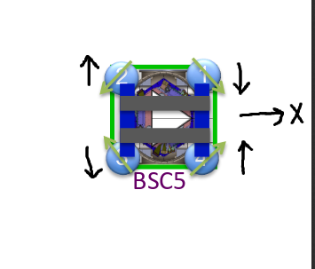
HAM6 ISI shaking
High vibration coupling has been noted at HAM6 (Link, Link), which contains the OMC and GW diodes. It is associated with motion of the table, with the vibrations coming up through the ISI suspension (Link), and some damping remedies have been suggested to mitigate coupling through the suspensions (Link, Link).
Figure 3 shows results from shaking by injecting bands of uniform noise using the ISI actuators. The solid symbols are made by multiplying the level produced by the injection in DARM by the ratio of the ambient motion amplitude to the injection amplitude in the sensor signal from the GS13s. This provides the plotted estimate of the noise that the ambient background contributes to DARM. The unfilled symbols indicate that the injection did not produce features in DARM and so they represent upper limits to the ambient contribution to DARM.
The assumption in these estimates is that the feature in DARM increases linearly with injection amplitude. Figure 4 shows that DARM features appearing at the injection frequency increase approximately linearly with injection amplitude.
In addition to direct coupling, we found that vibrational coupling at HAM6, in certain bands, can produce up/down-conversion features in DARM as a result of intermodulation with the OMC dither. To illustrate this, the injections were split into frequency bands. The DARM spectrum features in red in Figure 4 were produced by ISI injection in the 800-1200 Hz band, including the red features in the 100 Hz region. The up/down-conversion features usually do not increase linearly with injection amplitude, so the red stars (stars indicate up/down conversion) should be thought of as indicating the factor by which the ambient level in the injection band would have to increase to produce the red features in the spectrum, and not the noise contribution to DARM at present ambient levels. Also, the up/down conversion stars are calculated by dividing DARM by the average ratio of ambient to injection in the 800-1200 Hz instead of the ratio at the frequency of the star on the plot.
The closest approach of the ambient estimates to DARM is near 1050 Hz, indicating that an increase in GS13 signal by a factor of a little more than 2 at this frequency would produce a feature in DARM. The GS13 signals are not stored at a high enough rate (currently 2048) to record this frequency and we propose that the sample rate should be increased, at least at HAM6, to record this band.
HAM6 blue cross beam shaking
Figure 5 shows estimates of coupling levels between HAM6 GS13 signals and DARM, but for an external shaker injection (mounted on a blue cross-beam) instead of an ISI actuator injection. The ISI and shaker injection results are similar in that they both show roughly the same sensitivity in the same bands (the bands associated with peaks in the ISI transfer function), but they are quite different in detail. We think that the likely source of the difference between ISI and shaker injections is that the drives on the HAM6 tabletop are at two different locations: the ISI actuators and the suspension points, and the table is not a rigid body at these frequencies.
We focused more on ISI injections than on shaker injections for the formal PEM injection program this time and, in view of the differences, we now think this was a mistake. Since we concentrate not on servo noise but on external environmental signals, the shaker injections, coupling in at the suspension points, represent more realistic estimates for environmental signals.
Figure 5 also shows the GS13 signals during the 400-800 Hz injection. While there was some noise injected in the region around 1000 Hz, the red points from the injection in that band show that the orange features could not have been produced by the excess noise from the 400-800 Hz injection. Also, the GS13 spectra illustrate what the ambient levels look like. Over much of the band the signal is flat, indicating the electronic noise floor. Estimates in such regions would overestimate the ambient contribution to DARM, but in the regions where we made estimates of the ambient contribution, we made sure that the GS13s were not flat, indicating that they were “seeing” ambient motion.
We also shook in the 1200 - 7200 Hz band (not shown). The GS13s give signals out to 1800 Hz (test points, not stored) so we are not sure of the injection levels, but the injection level produced motion at a couple of orders of magnitude over background when it was in band. We saw no features produced in DARM for this level. Even higher levels, though (estimated to be about 3 orders of magnitude above ambient), did produce up and down conversion features that are apparently produced by beating with the 4100 OMC dither frequency. Any such environmental signals would be monitored by the 16k microphones and the 16k accelerometer on HAM6.
The HAM6 shaker injections suggest that increases over ambient of less than a factor of 5 will appear in DARM near 75 Hz, near 370 Hz, and in the 850-1100 Hz band.
HAM2 ISI shaking
Figure 6 shows results of ISI actuator injections at HAM2. Unlike HAM6, we saw no up/down conversion for injections that increased the motion by a couple of orders of magnitude. In addition to the 800-1200 Hz ISI suspension resonance band, HAM2 is sensitive in the 200-300 Hz band, with the contribution of ambient motion at 225-229 Hz expected to be within a factor of 2 or 3 of the DARM floor.
The high coupling at HAM2 may be associated with the unsuspended mirrors that touch the main beam, the two mirrors in the in-vacuum periscope and the 2 steering mirrors just upstream of the mode cleaner. The sharp peak at 227 Hz is likely an optic resonance, possibly the periscope.
Other chambers
Prior to the start of O1, Robert and his SURF student Katie Banowetz shook every chamber at the LHO corner station using shakers attached to blue cross-beams, HAM1, HAM2, HAM3, HAM4, HAM5, HAM6, BSC1, BSC2 and BSC3. For shaking at about 2 orders of magnitude above background, features in DARM were only seen for HAM6 and HAM2. The end station chambers were postponed to the PEM injections but time again ran out. These chambers should probably be shaken during the O1 run.
Potential scattering sites
During PEM injections, we shook a number of potential scattering sites that had been identified in photographs taken from the point of view of the test masses (Link). These included the valve seats just beyond the test masses, the beam tubes between HAMs 2 and 3 and between HAMs 4 and 5. For shaking at about 2 orders of magnitude above ambient in the 50-7000 Hz band, we did not see features in DARM.
PSL table
The PSL table is one of the most sensitive vibration coupling sites at acoustic frequencies, (see below) but shaking with a table-mounted shaker below 40 Hz did not produce detectable coupling. The upper limits are shown in Figure 7.
Coupling functions for vibration sensors
Figure 8 shows a compilation of coupling functions (meters of test mass motion per meter of sensor motion) for both global and local shaking. The coupling functions can be multiplied by the level of the signal from the sensor indicated in the legend for an estimate of the noise in DARM produced by that level of motion. The accuracy of this prediction depends on how close to linear the coupling is.
Acoustic injections
Figure 9 is a summary of acoustic coupling, showing, for all stations, the coupling functions for all injections that produced features in DARM, and the estimated level of noise in DARM for ambient sound levels. The coupling functions can be multiplied by the level in the particular microphone indicated in the legend in order to predict the resulting level in DARM. The estimated ambient levels show the estimated ambient contribution to DARM. In addition, the ratio between the estimated ambient levels and the DARM floor indicates how much larger the SNR would be in the environmental channel than in DARM (if the estimated ambient is 1/10 of the DARM floor then the SNR would be 10 times greater for an event produced by the environment. The plots are for linear coupling and do not show up or down-conversion coupling but, like the vibration summary, they show warning bands where non-linear coupling may occur.
Figures 10-15 show the sources of the data for Figure 9 and include up and down-conversion. Figure 10, for example, shows, in the top plot, four different band limited injections as seen on the vertex microphone. The DARM spectra for each injection, in the lower plot, are the same color as the injection trace. The bands were chosen to highlight the up and down conversion from intermodulation with the OMC dither. The orange 700-1200 Hz injection produces features around 2000 Hz and in higher bands, as well as in the 10-120 Hz region. The lower plot also shows the estimated contribution to DARM of ambient levels of sound, assuming linearity. Notice that the estimated levels are the same factor below the DARM noise produced by the injection as the injection level is above the ambient sound level. Upper limits (when no signal is induced in DARM or the sensor is at its electronic noise floor for ambient sound level) are also indicated, as well as the up/down conversion levels.
The estimated ambient points indicating up/down conversion from intermodulation are made by dividing DARM during the injection by the ratio of injection/ambient in the 700-1200 Hz band. We use the average for that band. However, this is only a rough estimate, as the injection amplitude varies over the band and the upconversion is likely produced at very specific resonances within the injection band. And, of course, the estimated ambient level for up/down conversion is an upper limit since the coupling is non-linear.
Robert, Anamaria