Jenne, Jim, Sheila
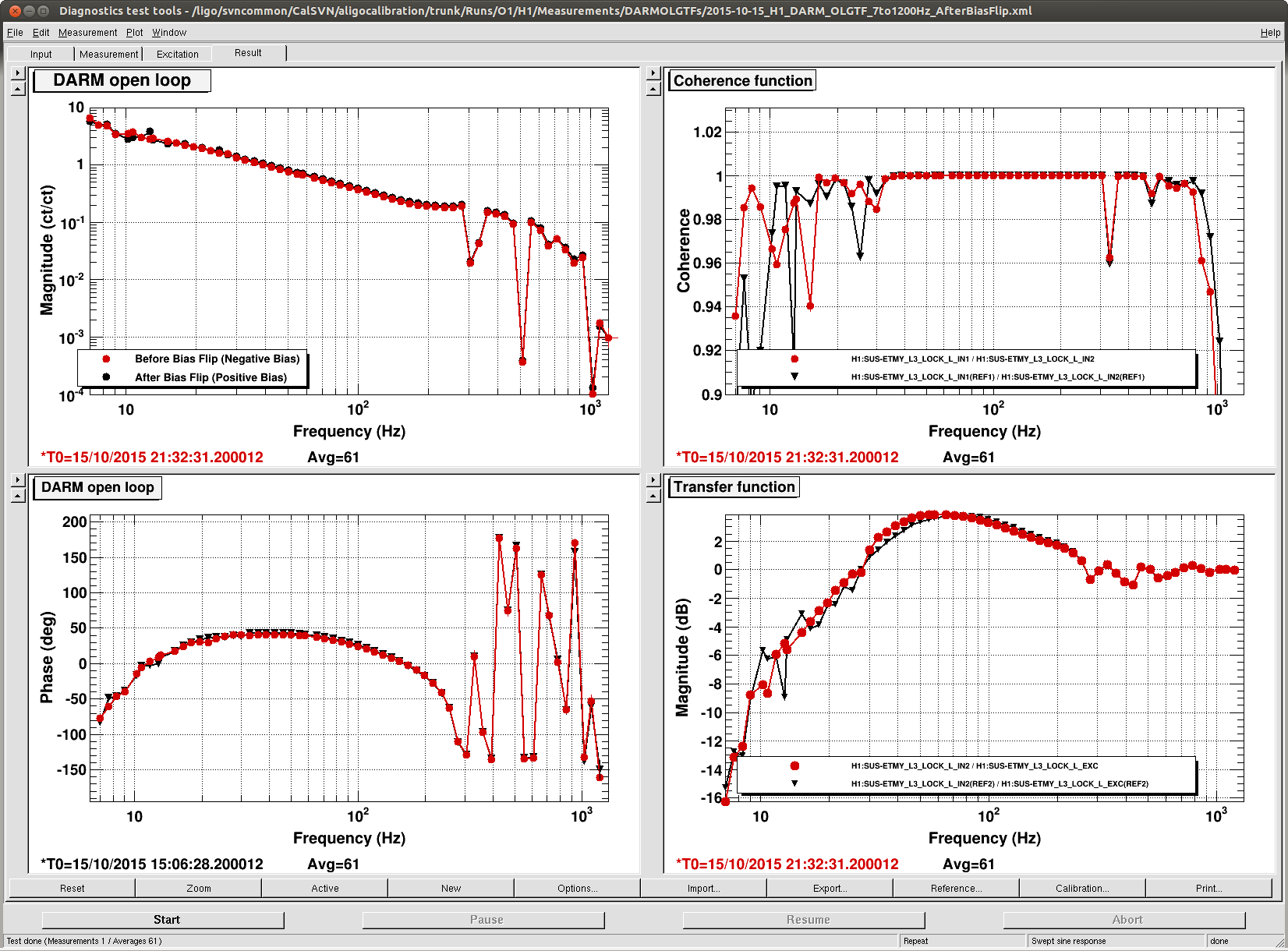
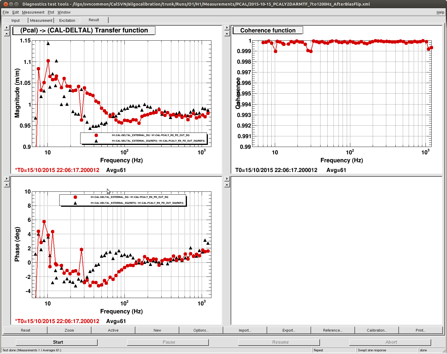
This morning we are trying to flip the bias sign on ETMY with high ground motion. This has caused a few locklosses, and since we currently have moderately high ground motion (20 mph winds, normal microseism) it is difficult to relock.
This gave us a chance to relook at the locklosses durring the early stages of CARM offset reduction, that are currently the biggest problem we have with locking durring modestly high ground motion (see here). A few weeks ago I had added pulling the OMC off resonance to the guardian (as is done at LLO) alog. I think that the OMC was probably not part of the problem, it is just that when the ground is moving more we get more fluctuations in the power at the AS port, which tended to cause the OMC to flash when it was on resonance.
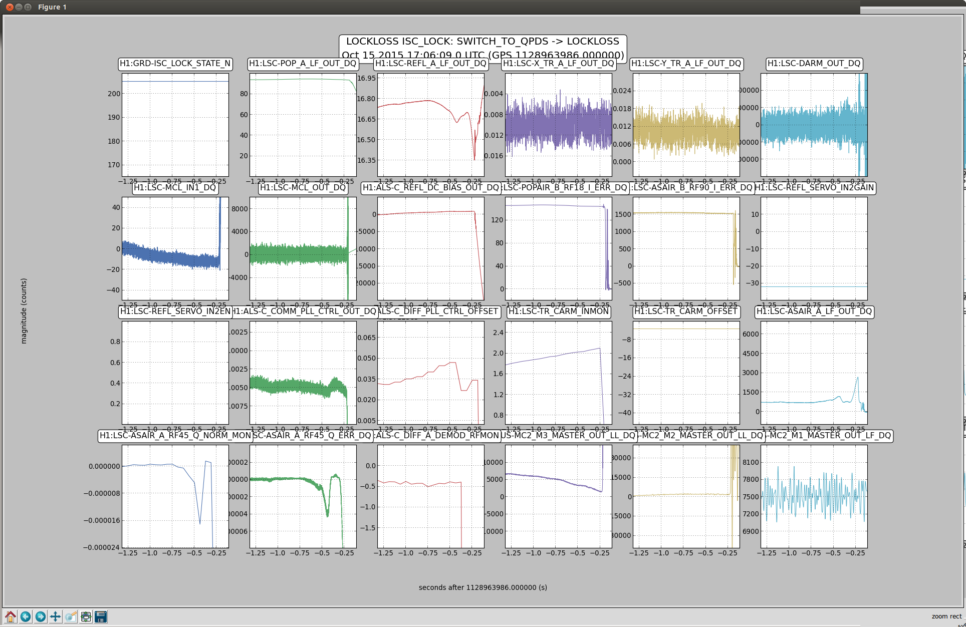
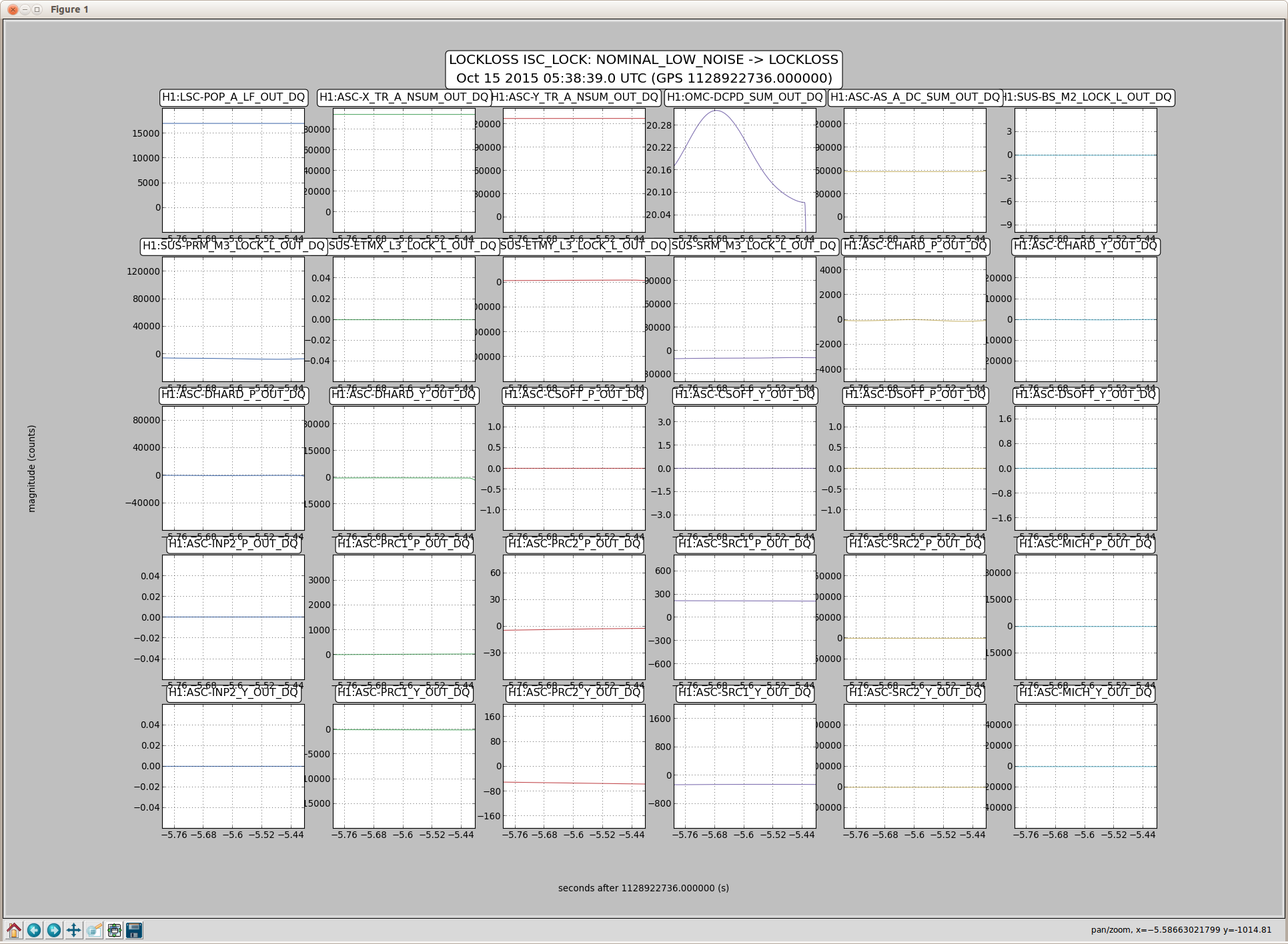
In the locklosses durring the switch to QPD step, the first attachment is fairly typical. We have glitches of about 1/10 of a second that happen as the CARM offset is reduced, and show up as dips in REFL LF, AS LF, AS_C, and AS45 Q. You could imagine that this is caused by an alignment fluctuation, but I have looked at optical levers and witness sensors for many of these locklosses and don't see anything. It seems more likely that these "glitches" are from the ALS DIFF loop, because as soon as we transition to RF DARM they stop.
One thing that I've seen is that because AS_C sees these glitches, the loop that sends AS_C to SRM and SR2 has a large glitch when these happen. This morning we edited the gaurdian to turn off both of the SRC loops in the state TR CARM (after the ASC is offloaded, when the refl WFS loops are turned off), and turn them back on in ENGAGE_ASC_PART1 (beofre turning on any other loops). We used to always have these loops off durring CARM offset reduction so we think this should be OK. However, it didn't completely solve the problem.
In this state we run an ezca servo that takes the AS45Q signal and adjusts the ALS DIFF offset. For some but not most of these SWITCH_TO_QPD locklosses it looks like this servo isn't able to keep AS45Q at zero because it simply doesn't have enough gain. For this reason we also tried increasing the gain of this servo in the switch to QPD step by a factor of 2 (to -82222). There are other locklosses however where this isn't the case. Also, in many of the glitches that we survive, the glitch is over before the servo reacts, which makes it seem like we need more proportional gain in the servo (its just an simple integrator).
Perhaps the best solution would be to try transitioning to RF DARM at a higher CARM offset. We occasionally have difficulty with the RF DARM transition at the current offset (sqrt TR CARM = -3.3, which should be about 140 pm carm offset depending on alignment) when the inital alingment is not good. If we move the transition to a lower CARM offset we will become more sensitive to inital alignment. One idea would be to try engaging the SOFT loops durring the CARM offset reduction to help compensate for a bad inital alignment.

