christopher.biwer@LIGO.ORG - posted 18:59, Thursday 24 September 2015 - last comment - 20:52, Thursday 24 September 2015(21924)
End of impromptu hardware injection testing and update to scheduling file
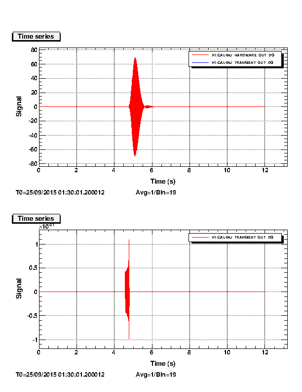
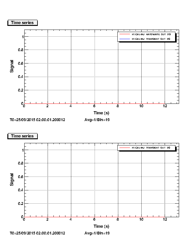
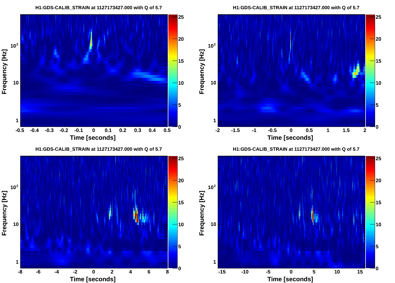
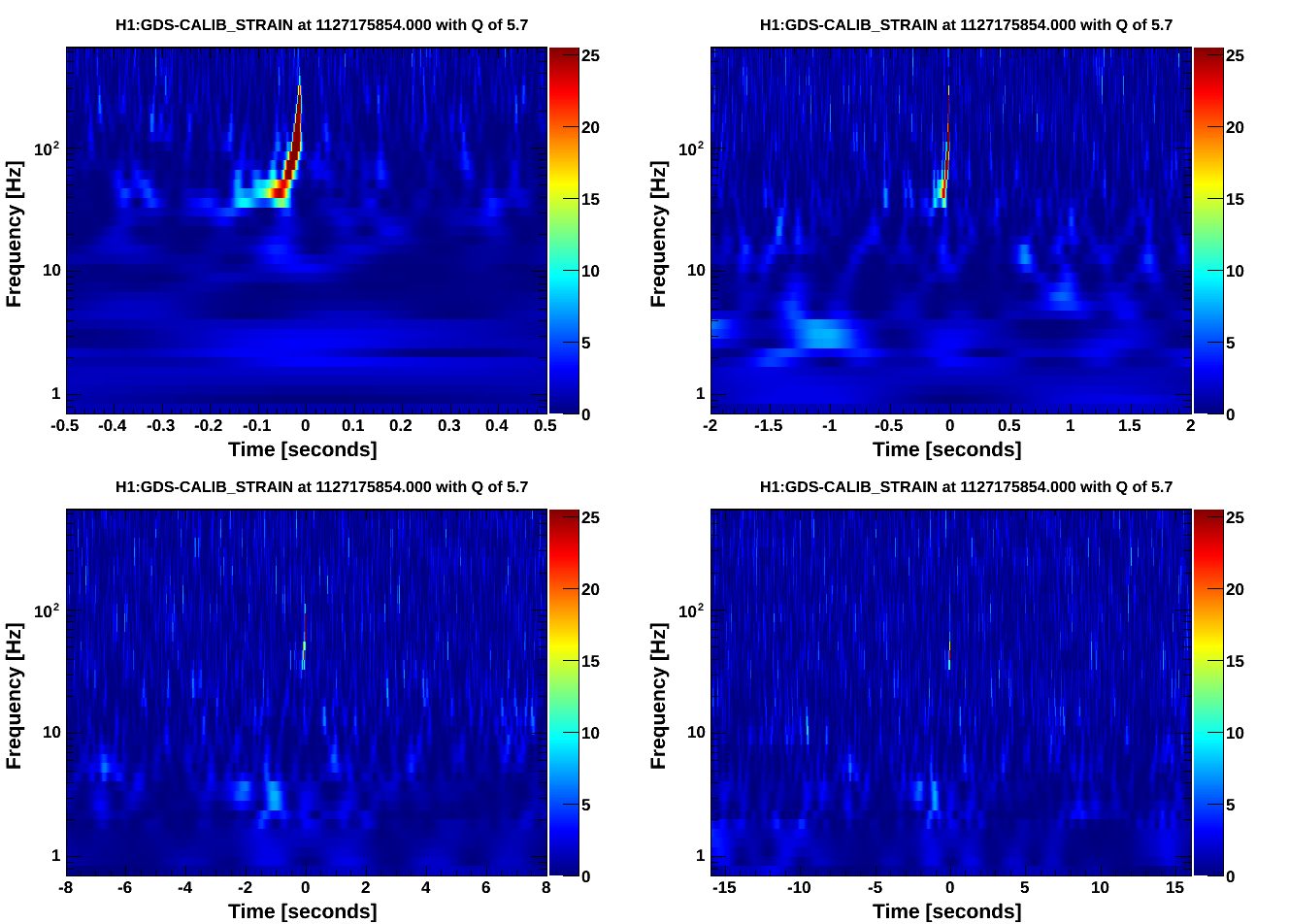
Adam, Alex U., Chris, Mike L., Eric

With a bit of effort we have successfully scheduled and injected a coherent CBC hardware injection. We have scheduled three coherent hardware injections for later tonight at 1127179817, 1127181617, and 1127183417. Those injections are the last of the night.

Here I will summarize what has happened.

All attempted/successful injections used the H1L1 coherent waveform from aLog 21838.

The are a couple differences between the sites. LLO uses monit to run tinj, whereas LHO does not. LLO uses the new hardware injection SVN, whereas LHO uses the DAC SVN still. The directory to run tinj at both sites is /home/hinj/Details/tinj.

Note that the times below are not the end time of the inspiral but rather this is the start time of injecting the ASCII file. The end time of the inspiral is listed on the gracedb page for the hardware injection and is ~6.986 seconds after the injection was scheduled.

Adam and Chris set out to do a H1L1 coherent hardware injection. See 21901.

We initially tried to scheduled a hardware injection at 1127175848. However the first step, i.e. to upload a GraceDB entry did not work. Chris was given a permissions warning and denied to upload to the CBC group.

The second attempt was scheduled for 1127168901. This was unsuccessful.
  * A gracedb page was generated for this hardware injection H1 and L1. No explanation for why Chris had permission this time.
  * At LLO the wrong schedule file was updated so there was no injection at LLO.
  * At LHO tinj had stopped before the time of the injection so there was no injection at LHO.

We then stopped the tests and went to the hardware injection telecon.

On the hardware injection telecon we had a group debug session.

We had to get tinj running at LHO again. To do this we did:
cd /home/hinj/Details/tinj
./run_tinj &

After running this command tinj was running again with process ID 11229. We tailed the log file (/home/hinj/Details/tinj/tinj.log) and saw that it was updating again.


Even though tinj is running in the background it still prints output to stdout. So Chris logged out of h1hwinj1 and logged back into h1hwnj1. tinj was still running.

The thought for the tinj failing was that when Chris edited the schedule file (/home/hinj/Details/tinj/schedule) the MCR environment that was used for testing monit received an error. Eric had checked the run_tinj log (/home/hinj/Details/tinj/run_tinj.log); note run_tinj is a wrapper to run tinj in monit. The log said:
ERROR: Unexpected error in tinj.
GPS=1127167412

So we did another test with tinj. The tests were logged in 21911.

The third attempt was scheduled for 1127172657. This injection was unsuccessful.
  * tinj stopped. Debugging by Eric showed that we need to change the filename of the waveform single-column ASCII files. Inspiral waveform files need have _H1 or _L1 at the end. So we renamed coherenttest1_*.out to coherenttest1_*_H1.out and coherenttest1_*_H1.out.
  * We also had to include a _ at the end of the filename in the schedule. So the line should have read "1127172657 1 0.5 coherenttest1_1126257410".

We made these corrections. But LLO went out of lock.

The fourth attempt was scheduled for 1127173421 and it was H1 only. It was successful.
  * The waveform was injected and observed going through the hardware injection filterbanks.
  * It had a scale factor of 0.5 applied.
  * A gracedb page was generated for this hardware injection H1 and L1.

Now that we had tinj running and a successful injection at LHO we waited for LLO to come back.

The fifth attempt was scheduled for 1127175848 and was a H1L1 coherent injection into both detectors. It was successful.
  * This was the first scheduled coherent CBC injection in aLIGO.
  * It was observed in both detectors. There was a CWB trigger for this event in gracedb and it was flagged with the INJ tag.
  * A gracedb page was generated for this hardware injection H1 and L1.

We then scheduled three more injections for the night at 1127179817, 1127181617, and 1127183417.

The schedule file now reads:
1127168901 1 0.5 coherenttest1_1126257410
1127172657 1 0.5 coherenttest1_1126257410
1127173421 1 0.5 coherenttest1_1126257410_
1127175848 1 1.0 coherenttest1_1126257410_
1127179817 1 1.0 coherenttest1_1126257410_
1127181617 1 1.0 coherenttest1_1126257410_
1127183417 1 1.0 coherenttest1_1126257410_

More plots and followup to come later.

An action item is to update the hardware injection documentation with the correct filename format and the commands to restart tinj on the command line.

And I will add as another note, to get to the monit web browser interface. On a controls machine you can type for the URL "http://h1hwinj1/" and it will take you to the monit web browser interface. At the moment I see no way to manage tinj this way but once we switch to monit this will be a good thing to remember.
Comments related to this report
Images attached to this comment