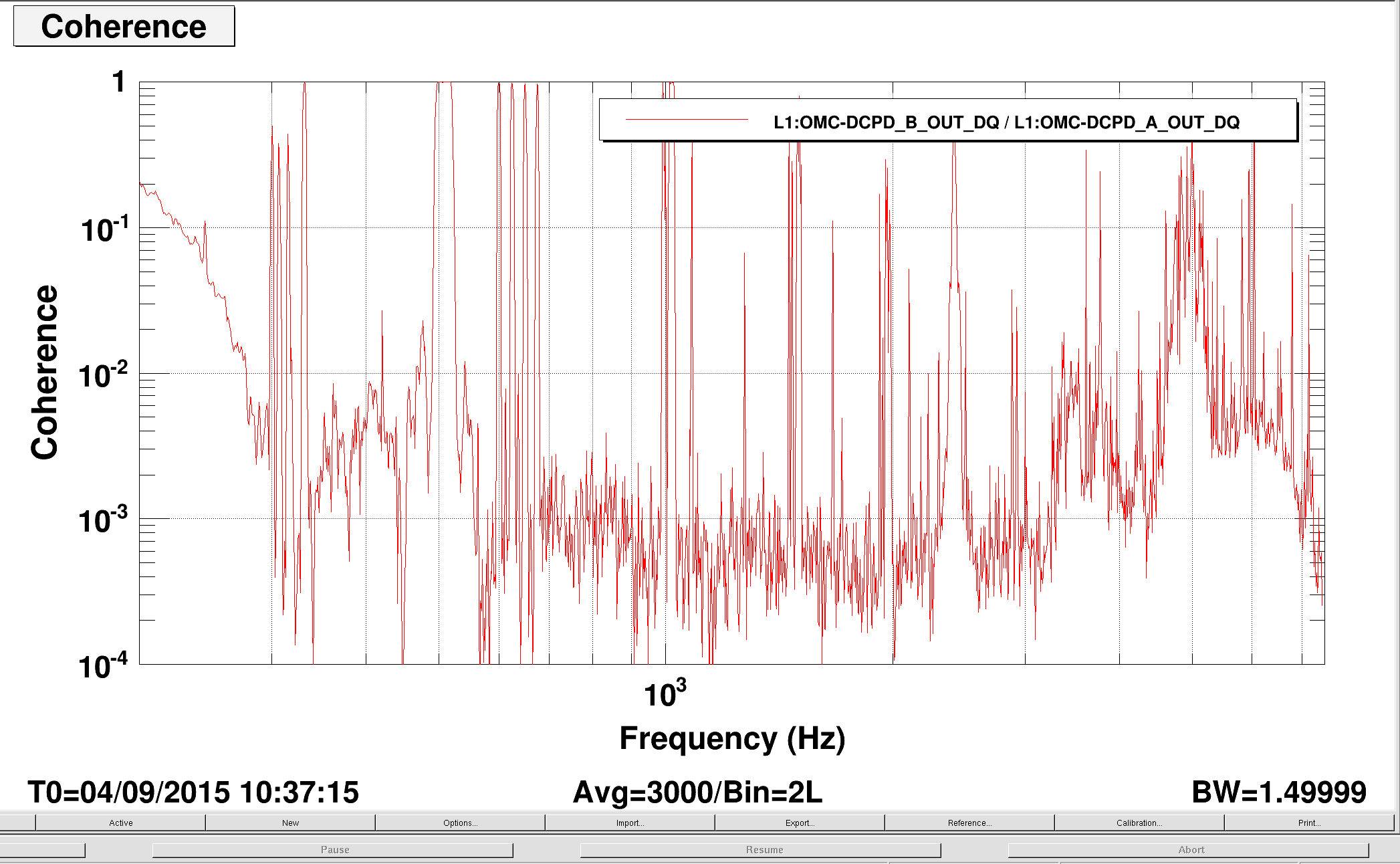
In this morning, I checked the OMC DCPD electronics chain (for both A and B) by injecting known sine wave analog signal. This was one of those items that Keita suggested me a while ago.
According to the data, I am concluding that our calibration model needs to add another pole at 10-ish kHz for accurately simulating the OMC whitening circuits.
Method
The measurement method is straightforward -- it is a swept sine measurement in a manual way.
I had a function generator by the HAM6 electronics rack which drove a single-ended-to-differential convertor (D1000931, technically speaking this is a coil driver test box). Then the differential signal is sent to the input of the OMC DCPD whitening board (D1002559, S1101603) by some clipping technique. By the way, the actual cable for connecting the OMC DCPDs were unplugged during the measurement. The excitation amplitude was set to 2 Vp-p at the function generator which resulted in 2 Vp-p in both positive and negative paths at the input of the whitening board as expected accroding to the schematic of the coil driver test box.
I then recorded the data in IOP at the full sample rate using dataviewer for 1 sec for a selected excitation frequency (and for some reason, diaggui did not want to run and hence dataviewer this time). Keeping the same excitation amplitude, I manually stepped the freqyency from 8 kHz to 100 Hz. After every step, I saved the time series of the IOP so that I can make a transfer function later. In addition, I had an oscilloscope with me which kept monitoring the excitation ampitude at the input of the whitening board. The scope told me that the excitation ampltude stayed constant at 2.02 Vp-p in each channel throughtout the measurement. The OMC DCPD had
Analysis and result
To get a transfer function from the data that I took in time series, I decided to do a sine-wave fitting for each data chunk to get the amplitude information. I wrote a small matlab script to do it. It can be found at:
aligocalibration/trunk/Runs/ER8/H1/Scripts/OMCDCPDs/Matlab/OMC_DCPD_AnalogChain_TimeSeries.m
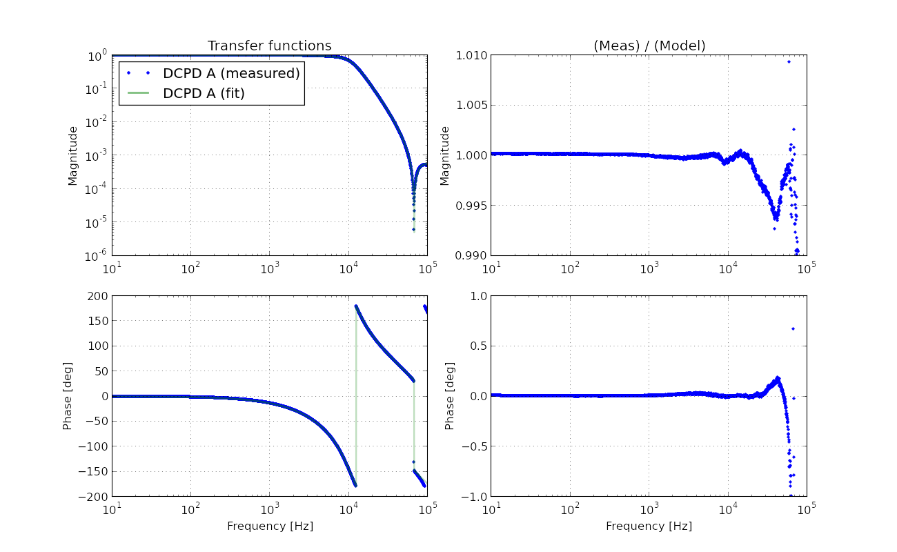
The script utilizes fminsearch and spits out the best fit amplitude for each frequency measurement. Additionally, it places uncertainty or error bar by taking the standard deviation of the residual. Note that this is not a standard way to place an error bar since it does not take the number of measurement points into consideration. According to the fit, the residuals were found to be usually a few counts which is much smaller than the amplitude of signals which was about 2000 counts. So it typically places 0.1% uncertainty after all.
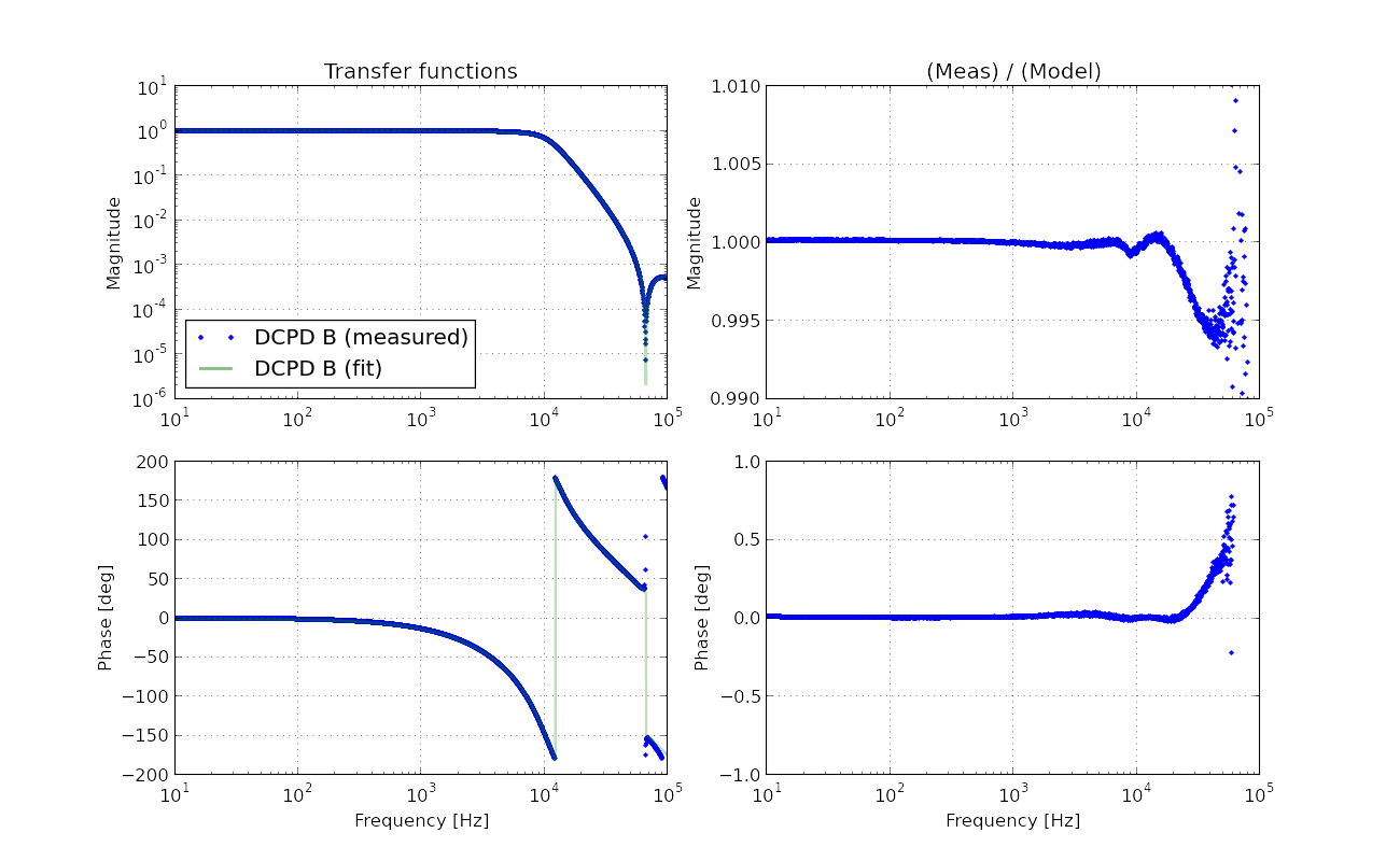
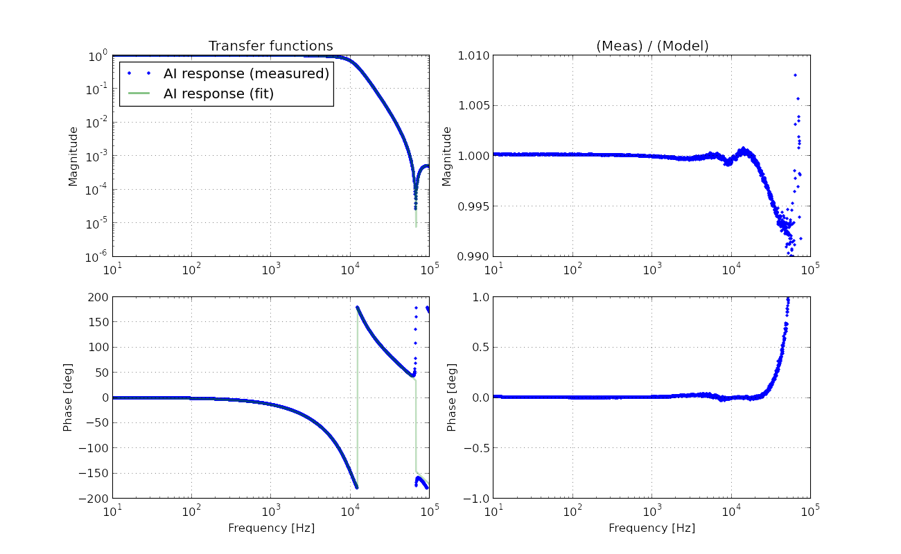
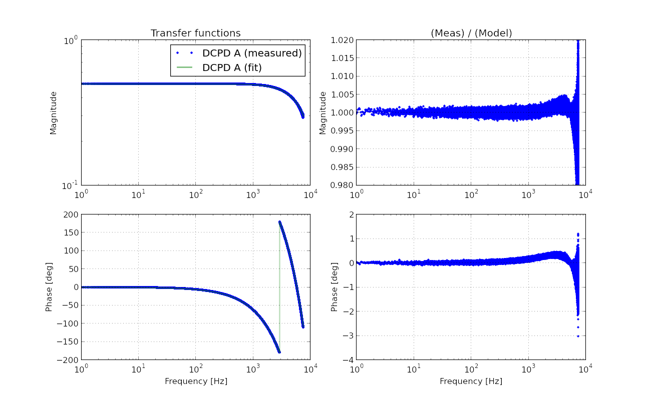
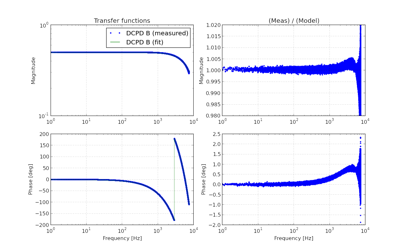
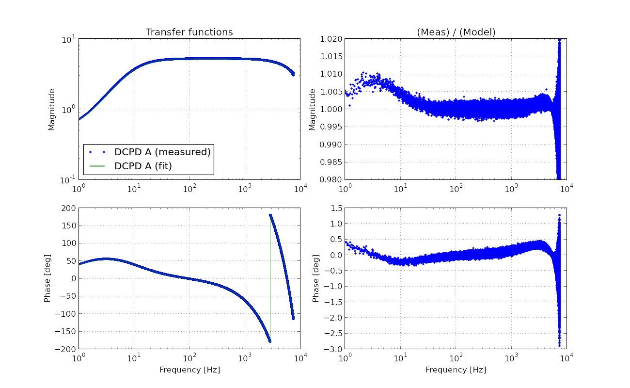
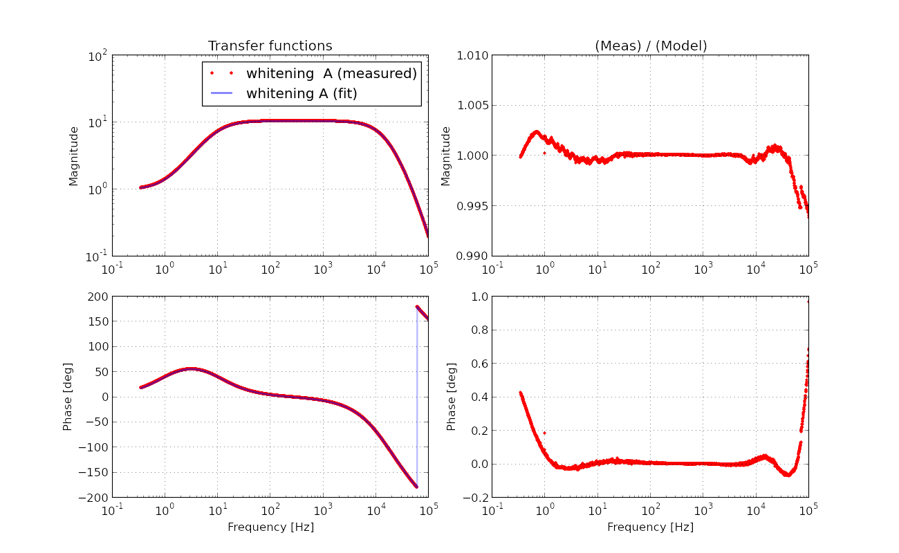
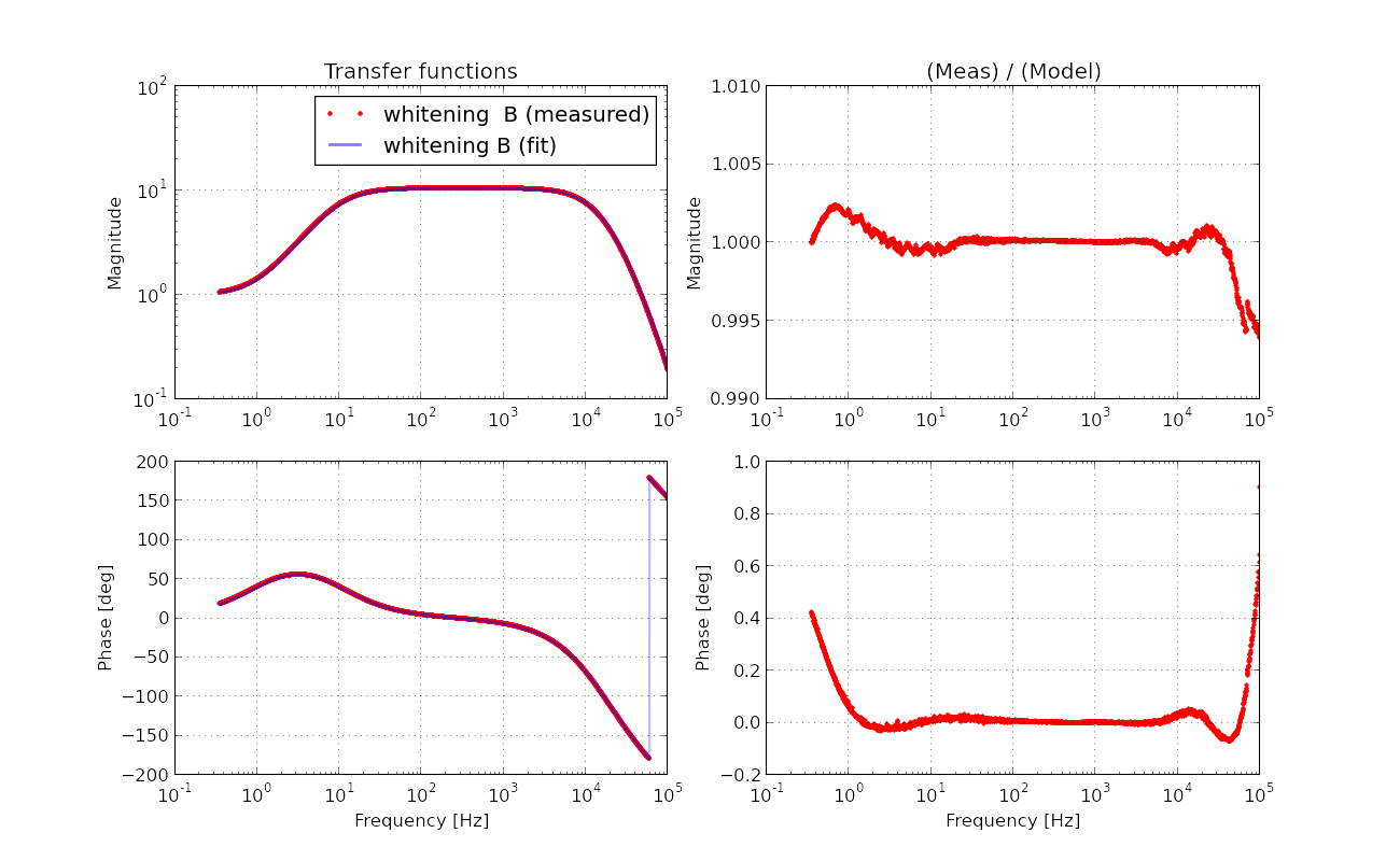
The result is shown in the attached pdf. By the way the lower panel in the plot says, "residual", but it should read "(measured)/(model)" instead. It shows the measured transfer function together with the expected model transfer function for comparison. It is very obvious that the measurement suggests that our model is missing some high frequency pole. The model is merely made of the analog AA response which I have already measured and fitted. Adding some random pole, I could see an extra pole at around 10.7 kHz making the fitting much better. In fact, I sort of knew that there seemed to be a high frequency pole by some other measurements which I did not post. We probably need to add this high frequency pole in our calibration model.


 .
.
[TJ, Jenne]
TJ pointed out to me that the Cal Hardware Injection ODC bit is red, and I tracked down where it's coming from. The ODC is upset that the CAL-INJ_HARDWARE limiter was turned off. I don't think that this has been preventing us from going to Observing mode, since the limiter was turned off on Thursday, but if it does (particularly if some updates have been made during maintenence day that tie this bit into our "OK" status) I will turn the limiter back on until the ODC can be updated to know that the limit switch should be off.
I have sent EricT an email asking for him to help figure out the ODC part of this.
Just to be clear, there should be NO ODC CHECKS INVOLVED in the IFO READY bit. ODC is only used as transport of the bits, and none of the checks being done by ODC affect IFO READY. The only thing that should be going in to IFO READY now is the GRD IFO top node. In other words, this ODC issue should not have been preventing you from going to Observing mode.
Note, when the EXC bit in the CALCS CDS overview is in alarm, we tend to open the screen CAL_INJ_CONTROL to attempt to diagnose - This shows a big red light for some ODC Channel OK Latch, leading us to misdiagnose what is actually in alarm. We have 2 operational problems:
1) If generically, there is a red light on the CDS screen - where do you go? Normally, we follow the logical medm and are able to get to the bottom of the red status via logical nested reds. This is not the case for the CALCS screen - the CDS H1:FEC-117_STATE_WORD bit is RED on the H1CALCS line of the overview screen, yet this bit is nowhere on the CALCS screen.
So, where does the info come from for specifically the EXC bit of the H1CALCS state word, such that we can do something about it?
2) Someone should rework the CAL_INJ_CONTROL.adl so that it doesn't cause us to misdiagnose actual reds. Currently, the HARDWARE INJECTIONS are out of configuration (outstanding issue to still be sorted) and yet, there is NO INDICATION of that on the CAL_INJ_CONTROL screen... Also, the CW injection appears to be off, but there is no "red alarm" on the screen.
BTW, the HARDWARE INJ appear to be off. They dropped around 7pm local time last night (20 hours ago).