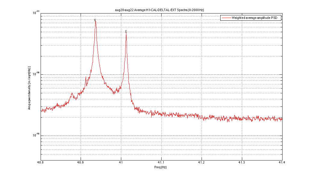
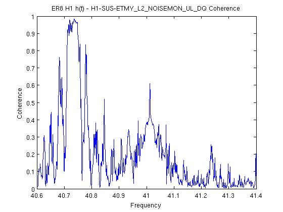
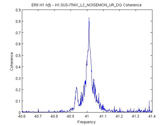
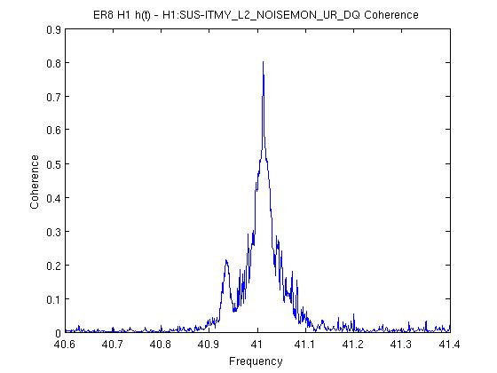
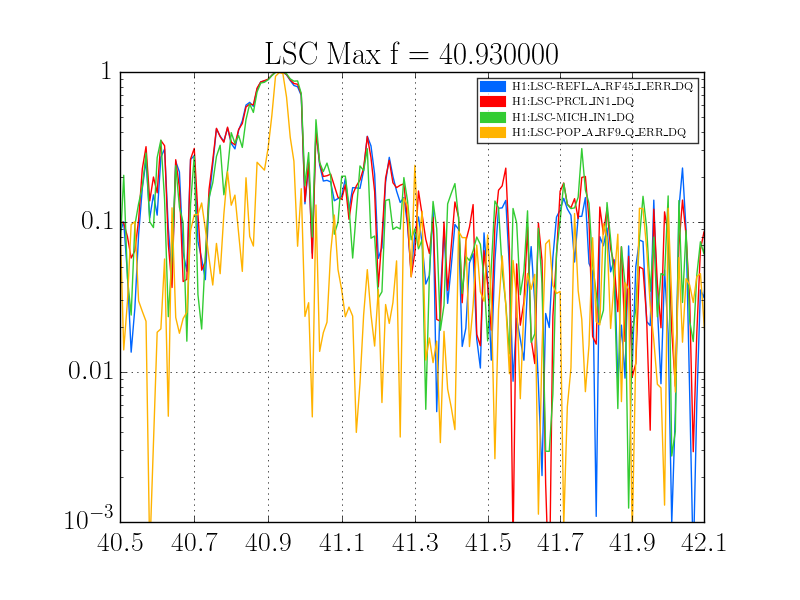
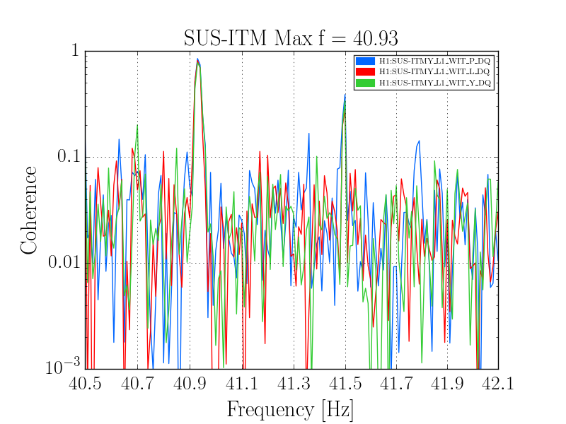
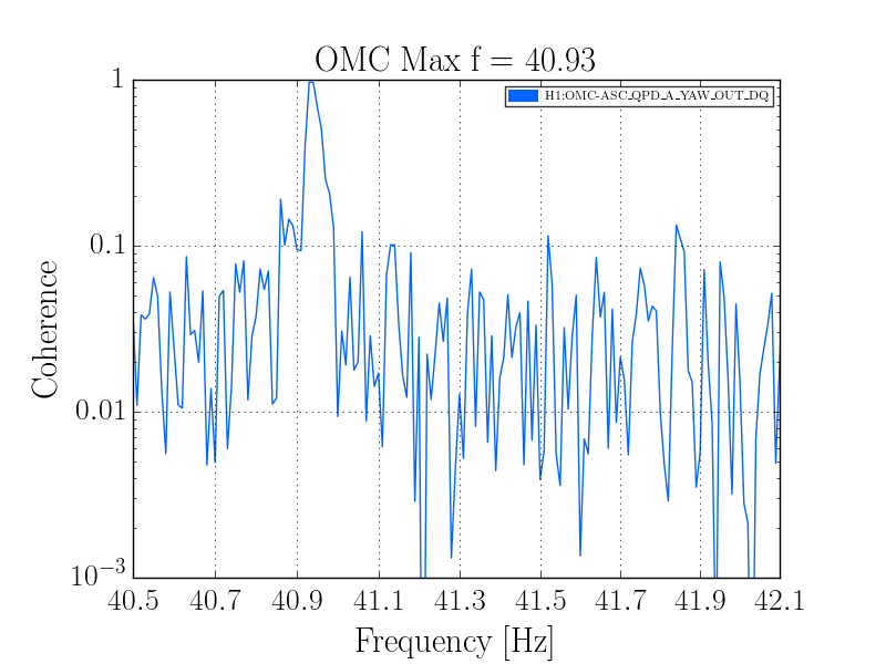
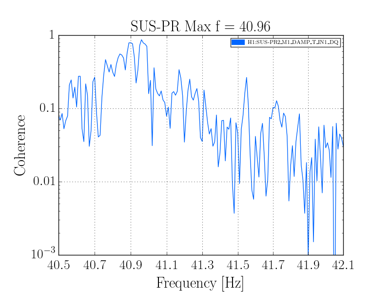
It was noted recently elsewhere that there are a pair of lines in DARM near 41 Hz
that may be the roll modes of triplet suspensions. In particular, there is
a prediction of 40.369 Hz for the roll mode labeled ModeR3.
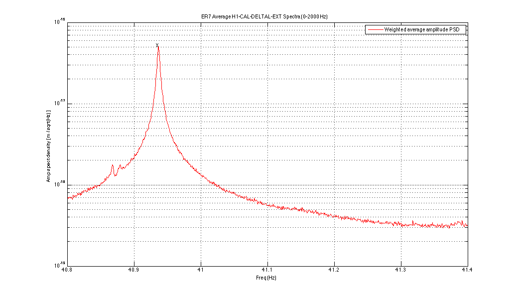
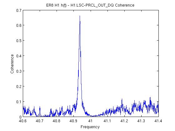
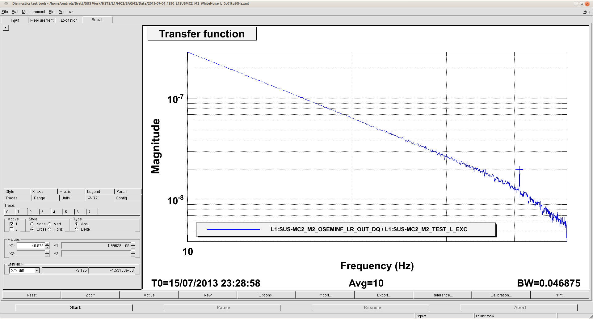
Attached is a zoom of displacement spectrum in that band from 50 hours of early
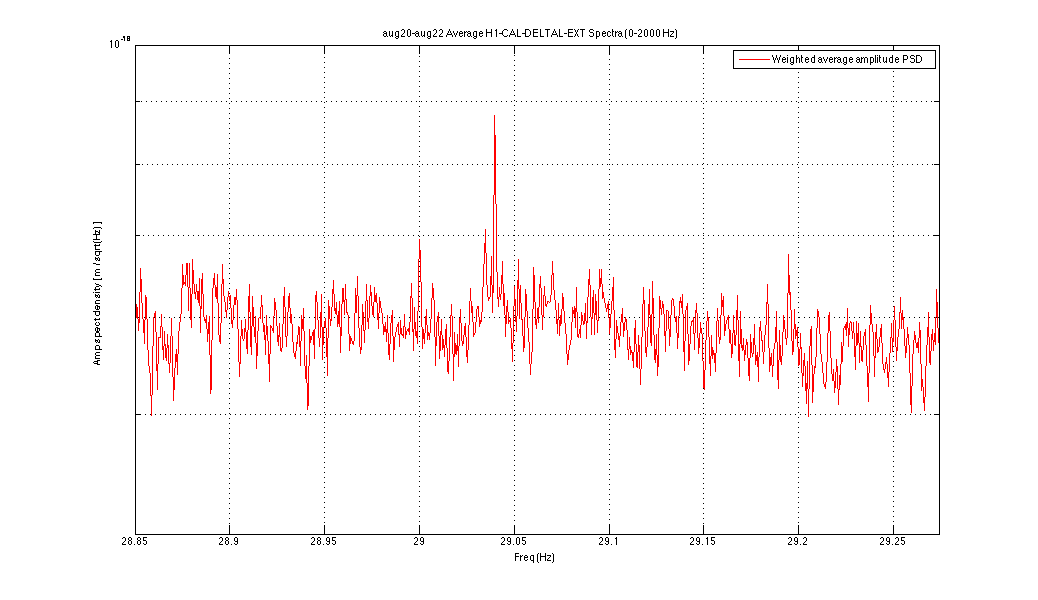
ER8 data. Since one naively expects a bounce mode at 1/sqrt(2) of the roll mode,
also attached is a zoom of that region for which the evidence of
bounce modes seems weak. The visible lines are much narrower,
and one coincides with an integer frequency.
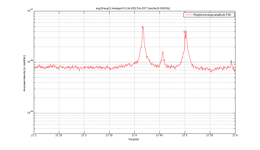
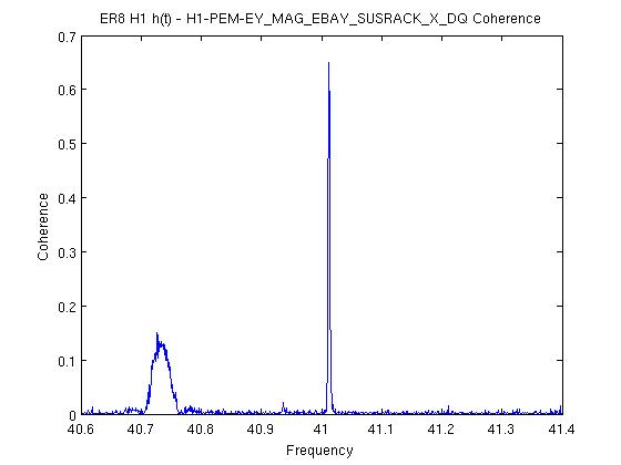
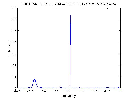
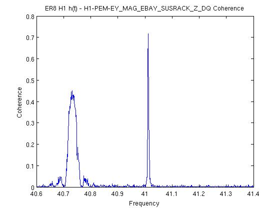
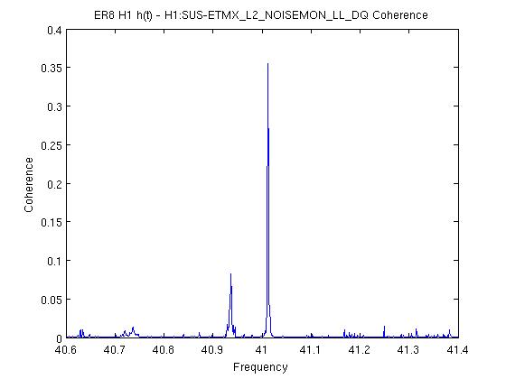
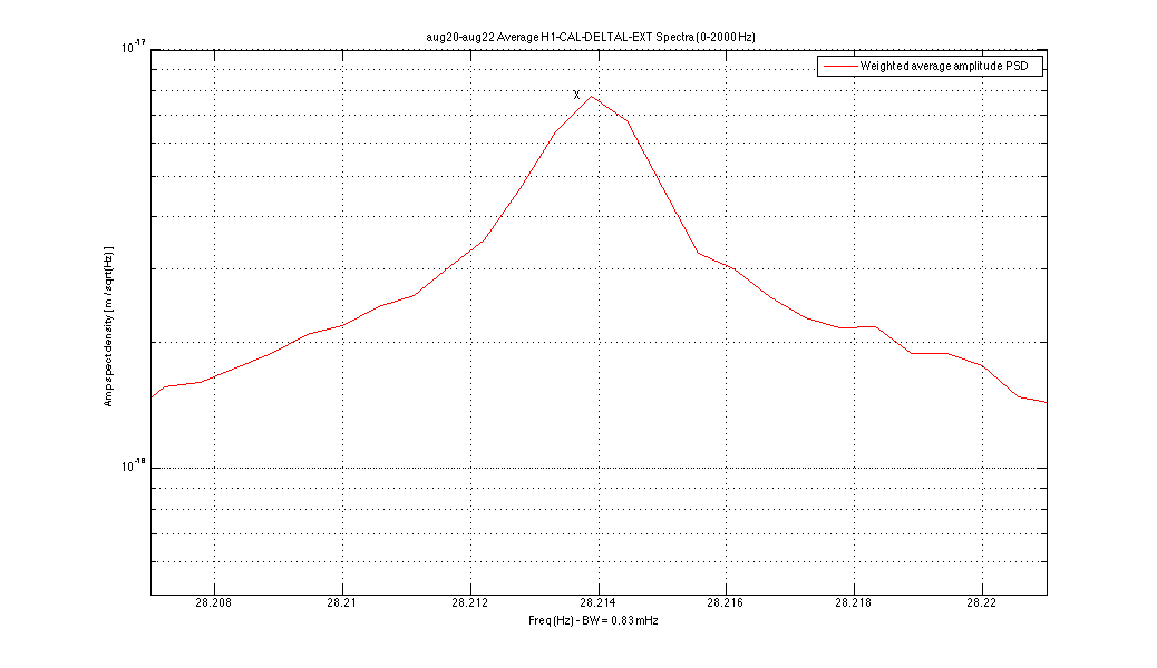
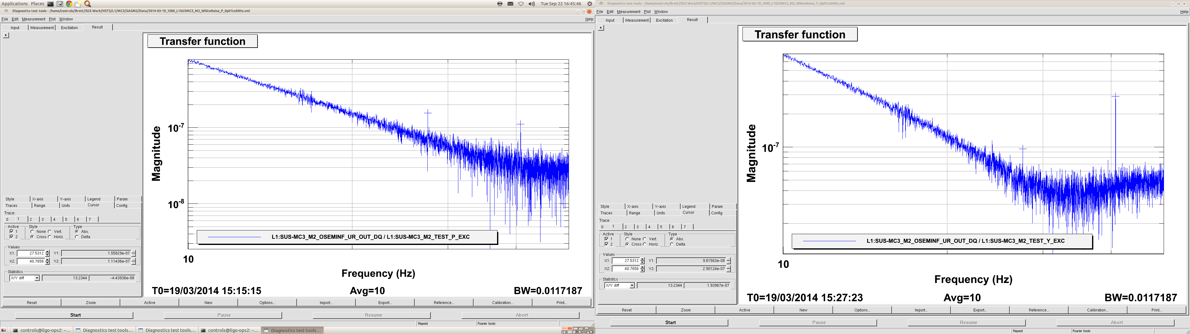
For completeness, I also looked at various potential subharmonics and harmonics
of these lines, in case the 41-Hz pair come from some other source with non-linear coupling.
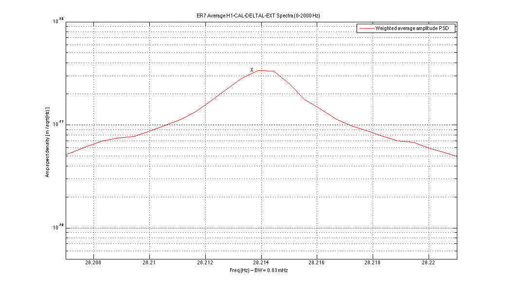
The only ones that appeared at all plausible were at about 2/3 of 41 Hz.
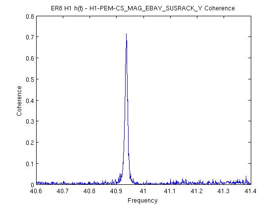
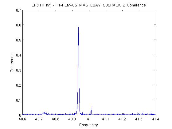
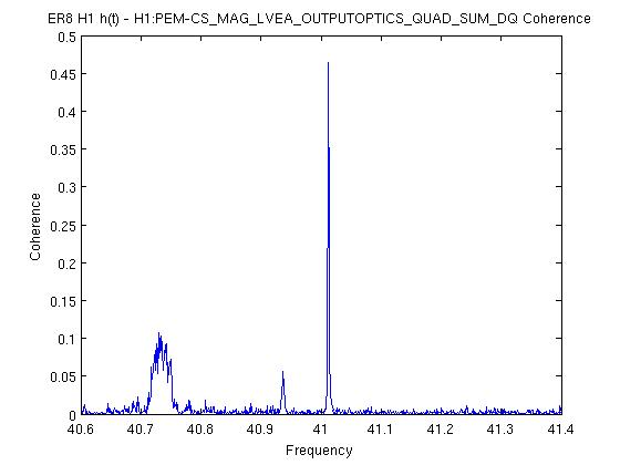
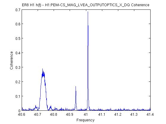
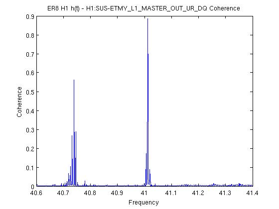
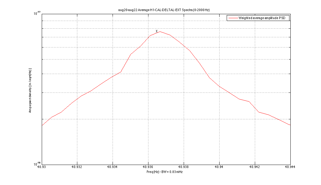
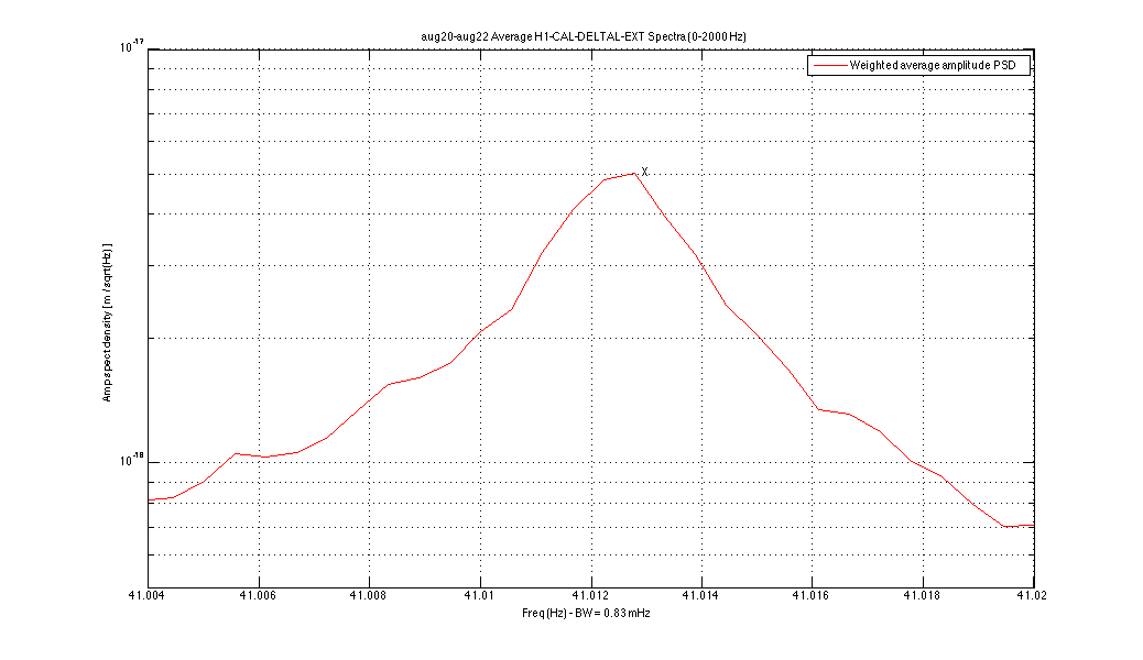
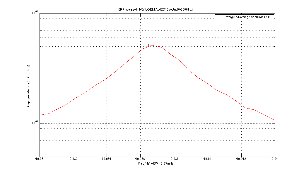
Specifically, the peaks at 40.9365 and 41.0127 Hz have potential 2/3 partners at
27.4170 and 27.5025 Hz (ratios: 0.6697 and 0.6706) -- see 3rd attachment. The
non-equality of the ratios with 0.6667 is not necessarily inconsistent with a harmonic
relation, since we've seen that quad suspension violin modes do not follow a strict harmonic
progression, and triplets are almost as complicated as quads. On the other hand, I do not see
any evidence at all for the 4th or 5th harmonics in the data set, despite the comparable strain
strengths seen for the putative 2nd and 3rd harmonics.
Notes:
* The frequency ranges of the three plots are chosen so that the two peaks would
appear in the same physical locations in the graphs if the nominal sqrt(2) and 2/3 relations were exact..
* There is another, smaller peak of comparable width between the two peaks near 27 Hz,
which may be another mechanical resonance.
* The 27.5025-Hz line has a width that encompasses a 25.5000-hz line that is part of a
1-Hz comb with a 0.5-Hz offset reported previously.


I'm looking for the "Like" or "+1" button.