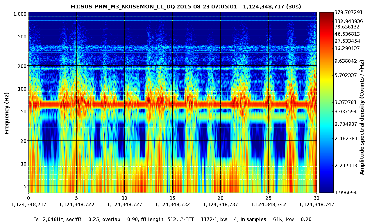
Displaying reports 67421-67440 of 85592.Go to page Start 3368 3369 3370 3371 3372 3373 3374 3375 3376 End
Reports until 20:26, Wednesday 27 May 2015
H1 CAL
kiwamu.izumi@LIGO.ORG - posted 20:26, Wednesday 27 May 2015 (18656)
ETM calibration using ALS diff VCO round 1

Jeff, Kiwamu,

In addition to the classic free-swing-Michelson technique, we did another calibration of the ETM responses using the ALS diff VCO.

We locked ALS diff and drove various stages of ETMs. The plan is to take out the loop suppression by using a measured open loop transfer function and calibrate data into meters through the known VCO calibration. The data and results will come later. A conclusion from todays's calibration is that the calibration of the ETMY ESD in the low voltage configuration is difficult to measure since the strength is so weak. So for the reason, we ended up measuring only the ETMY L2 stage and ETMX L3 stage. Sigh. In order to get a reliable calibration on ETMY ESD, we probably need the DARM loop closed in fully locked interferometer and need to make a comparison between well-calibrated ETMX ESD and ETMY ESD.

H1 SYS (DetChar, GRD, ISC, SUS, SYS)
sheila.dwyer@LIGO.ORG - posted 17:30, Wednesday 27 May 2015 (18655)
suspension saturation lockloss tool

Adrew Lundgren has written a script that can be easily used to identify which suspensions saturate in which order in a lockloss.  The script is in USERAPPS/sys/common/scripts/ and should work for LLO as well.   The script is called with a time which can be either a gps time or any format that tconvert accepts, it checks for suspension MASTER_OUT_DQ channels that go above 2^17 for 10 seconds before or after the time given.  This may be integrated with the summary pages and/or the graphical lockloss tool soon, but now it is ready to go from the command line.  For now it is not checking things like RMs, OMs, IMs, but they can be added if anyone wants them. 

Thanks to Andy for putting this together so quickly, and to Jamie, Johnathan Hanks, and Greg Mendell for helping to get it running here.  

sheila.dwyer@opsws2:/opt/rtcds/userapps/release/sys/common/scripts$ lockloss list
2015-05-27 03:47:29.151290  ISC_LOCK  INCREASE_POWER -> LOCKLOSS
2015-05-27 05:55:09.044630  ISC_LOCK  DC_READOUT -> LOCKLOSS
2015-05-27 06:26:54.136390  ISC_LOCK  DC_READOUT -> LOCKLOSS
sheila.dwyer@opsws2:/opt/rtcds/userapps/release/sys/common/scripts$ ./lockloss-sus-sat 2015-05-27 06:26:54.136390
First saturation at 1116743228.92 by SRM M3 LL
SRM M3 UR saturated at +0.0015
OMC M1 LF saturated at +0.0361
OMC M1 RT saturated at +0.0361
SRM M3 LR saturated at +0.1064
SRM M3 UL saturated at +0.1528
SR2 M3 LL saturated at +0.2544
SR2 M3 UR saturated at +0.2549
SR2 M3 UL saturated at +0.2563
SR2 M3 LR saturated at +0.2563
OMC M1 T2 saturated at +0.3252
OMC M1 T3 saturated at +0.3252
ETMY L2 LL saturated at +0.3545
ETMY L2 UL saturated at +0.3560
ETMY L2 LR saturated at +0.3579
ETMY L2 UR saturated at +0.3706
ETMY L3 UL saturated at +0.3730
ETMY L3 UR saturated at +0.3730
ETMY L3 LL saturated at +0.3730
ETMY L3 LR saturated at +0.3730
MC2 M3 UL saturated at +0.4136
MC2 M3 UR saturated at +0.4185
MC2 M3 LL saturated at +0.4375
MC2 M3 LR saturated at +0.4424
SR2 M1 T2 saturated at +1.2725
SR2 M1 T3 saturated at +1.2725
ETMX L1 LR saturated at +1.2959
ETMX L1 LL saturated at +1.2969
ETMX L1 UR saturated at +1.3232
ETMX L1 UL saturated at +1.3242
ETMY L1 LL saturated at +1.5869
ETMY L1 LR saturated at +1.6074
ETMY L1 UL saturated at +1.6123
ETMY L1 UR saturated at +1.6318
PRM M3 UR saturated at +2.5864
PRM M3 UL saturated at +2.6104
PRM M3 LR saturated at +3.2441
PRM M3 LL saturated at +3.2832
PRM M2 LR saturated at +3.6689
PRM M2 LL saturated at +3.7305
PRM M2 UR saturated at +3.7900
PRM M2 UL saturated at +3.8564
 
H1 AOS (ISC)
eleanor.king@LIGO.ORG - posted 16:01, Wednesday 27 May 2015 (18651)
SRC length results summary

Keita, Kiwamu, Daniel, Elli

We have measured the SRC length to be 56.013+/-0.0035m.  This is 4.8+/-3.5mm longer than the design SRC length of 56.008m.   
This result is consistent with an earlier measurement of the LHO SRC length of 56.015(+/-.005)m (alog17451).  (This earlier measurement which was considered questionable due to signal-to noise issues and a lack of SRMI angular control.)

Method:
See alog 18263 DRMI was locked with wavefront sensors on for alignment control.  An auxiliary NPRO on IOT2R was sent into the interferometer through the back of IM4.  The Aux laser was coaligned with the PSL using the PSL transmission through IM4 onto IOT2R, and the prompt reflection of the Aux laser onto IM4. The auxiliary laser frequency was locked at a frequency offsets to the PSL using a PLL, and this frequency offset was swept to measure the Aux laser power reflected from DRMI as a function of frequency.

The DRMI reflection coefficient is a function of frequency because Mich reflectivivty varies with frequency. This is due to the 8.9cm Schnupp asymmetry, and Michelson reflectiviy = cos(2*pi*f//c*ScnuppAsymmetry). When DRMI is locked, the PSL light is totally reflected from Mich, and DRMI reflectivity looks the same as the PRC reflectivity.  At 842.7 MHz offset from the PSL frequency, Mich transmissivity is 100%, and DRMI looks like a cavity between the PRM and SRM mirrors and with the length of SRC+PRC combined.  As the PRC length is already known (alog 10642), we can measure the DRMI reflectivity around 842.7MHz by sweeping the Aux laser through +/-842.7MHz offset from the PSL frequency.

The reflected  beatnote of the PSL and the Aux laser read out at relfair path. The frequencies of the transmission dips closest to +/-842MHz were fitted using a lorentzian function. The number of fsrs (N) between peaks at ~+842MHz and -842MHz were determined.  This determines the fsr and the length of the combined PRC/SRC cavity.

df=positive_peak_frequency-negative_peak_frequency
vfsr=N*df
LSRC=c/2/vfsr-LPRC;

Analysis:

Graphs of the reflected beatnote power vs aux laser frequecy offset are attached.  There is an 11MHz osciallation in the reflected power which is not yet explained.   The phase has had a linear phase term removed, but is not continous from sweep to sweep, perhapse due to small changes in the alignment of the aux laser to the psl over time.  There are peaks which appear every fsr, which I am assuming ar ehigher order modes, but I haven't looked closely at these yet.
Peaks were fitted at -842.14(0.02)MHz and +841.933(0.02)MHz, graphs attached.  
The number of fsrs between these peak frequencies is 1277.  (If the number of fsrs wer off by +/-1, the cavity length would differ by +/-10cm.  We had already estabilished from previous measurements that the SRC length is not off by this much.)
This corresponds to a combined PRC/SRC cavity vsfr=1.319MHz, and length=113.664(0.0027)m.  The PRC length was already measured by Evan et al (alog 10642) to 57.6508+/-0.0007m, so the SRC length is 56.013+/-0.0035m.
 

Images attached to this report
Non-image files attached to this report
H1 General
nutsinee.kijbunchoo@LIGO.ORG - posted 15:59, Wednesday 27 May 2015 (18654)
Ops Summary

[Morning Meeting]

SUS BSC 1 2 3 down


[Safety Meeting]

DON'T GET HURT!


[Activities]

8:41 Jeff & Sudarshan to EX (Calibration work)

8:45-9:20 Richard & Fili in CER working ITMX SUS

9:35 Richard to SUS 2B power (Electronics room)

10:00 Jeff & Sudarshan temprary back

10:12 Jeff & Sudarshan back to EY

10:28 Richard back

10:46 Rick et al. to EY to measure transfer functions

11:48 Fred and a guest to LVEA

12:16 Fred back

12:42 Jeff & Sudarshan back

12:58 Jeff B. to optic room

14:08 Kyle rolled up receiving door

14:17 Kyle done, receiving door closed


Happy Calibration Day

H1 SEI (CDS)
filiberto.clara@LIGO.ORG - posted 10:57, Wednesday 27 May 2015 (18650)
Powered cycled ISI Coil Drivers for HAM4/5
Will taking some current measurements for SUS racks this morning, Richard noticed that the ±24V power supplies for HAM4/5 (ISI Coil Drivers) had some oscillation in the current meter. We power down the ISI coil drivers (HAM 4 and 5), and the oscillation in the current meter disappeared. We powered the ISI coil drivers back on and oscillation in the current meter is no longer present.
H1 SUS (CDS)
james.batch@LIGO.ORG - posted 08:55, Wednesday 27 May 2015 (18647)
Restarted models on h1susb123
There was an ADC timeout error in the h1susb123 I/O chassis at 23:26 PDT yesterday night (May 26), which caused all of the user models (h1susbs, h1susitmx, h1susitmy) to stop running. I restarted all models without power cycling the electronics and the models restarted correctly.
H1 SUS
betsy.weaver@LIGO.ORG - posted 08:41, Wednesday 27 May 2015 - last comment - 08:59, Wednesday 27 May 2015(18646)
Starting ESD charge measurement on ETMx
Comments related to this report
betsy.weaver@LIGO.ORG - 08:59, Wednesday 27 May 2015 (18648)

Since it's the last opportunity to run a charge measurement on ETMx before the E7 run and immediate subsequent vent, I've started one now.  Attached are medm snapshots of the nominal ETMx ESD screen settings, and also with the measurement in mid-sweep.  I've followed the procedure Stuart outlines in his alog and TXT file at 17662.

Images attached to this comment
H1 ISC (CAL)
evan.hall@LIGO.ORG - posted 23:59, Tuesday 26 May 2015 - last comment - 00:11, Wednesday 27 May 2015(18642)
Calibration lines reduced for ETMY low-pass filtering

Sheila, Kiwamu, Evan

Using the same method as described here, we determined that the switching of the ETMY ESD low-pass filter appears to be working fine and is compensated for correctly in the ESD output filters. With offloading turned off and DARM controlled by ETMX, the transfer function ETMY L3 LOCK L → DARM IN1 is identical in both LPF states. It very similar to the transfer function ETMX L3 LOCK L → DARM IN, up to a constant factor of −50. This is a little mysterious to us, since we expect only a factor of 20 at dc between the high-range driver and the LVLN driver.

Anyway, we partially transitioned control of DARM to ETMX and ETMY (we had them actuating with about equal strength), and then saw that the ETMY ESD drive rms was about 30 000 ct, with most of the counts coming from the 322 Hz and 538 Hz calibration lines. We turned the line amplitudes down by a factor of 10 (from 2 ct to 0.2 ct). However, h1susb123 went down right as we were about to complete the transition to ETMY.

Comments related to this report
sheila.dwyer@LIGO.ORG - 00:11, Wednesday 27 May 2015 (18644)

The other piece of good news from tonight is that with tidal running the lock seems to be stable at 17 Watts of input power.  We saw an oscillation in both ITMs, when we tried to increase the power, but this may be because we were unable to actuate on ITMX.  

LHO General
cheryl.vorvick@LIGO.ORG - posted 23:53, Tuesday 26 May 2015 (18643)
Ops Eve Summary:

- thunderstorm early in the shift, tripped a panel alarm in the fire system

- Fire Department here to reset the pannel

- full alignment of IFO, after opening shutter at EX, then handed off to Kiwamu

- JeffK was at EY

- CP2 still in alarm after being filled

- RO water system is in alarm

H1 SUS (CDS, SUS)
sheila.dwyer@LIGO.ORG - posted 23:04, Tuesday 26 May 2015 - last comment - 10:36, Wednesday 27 May 2015(18640)
ITMX PUM AI chassis not working

Evan, Kiwamu, Sheila, Jeff

We noticed that we weren't really driving ITMX PUM.  Evan and I went to the racks and saw that the DAC outputs were changing, but the LED that says DAC WD next to the DAC input was not lit and there was nothing coming out of the AI board.  This is probably why Dan was unable to damp ITMX violin modes last night.

Comments related to this report
sheila.dwyer@LIGO.ORG - 23:46, Tuesday 26 May 2015 (18641)

h1susb123 has stopped running, the symptoms are verry similar to what happened yesterday.  There are several red block on the CDS overview screen, front end models are not synced to the IOP. 

This coincided with kiwamu pulling out the AI chassis for ITMX L2, although we aren't sure if this is related or not.  We don't know how to restart this without causing a problem for the dolphin network, so we're done locking for tonight. 

daniel.hoak@LIGO.ORG - 00:41, Wednesday 27 May 2015 (18645)

AH-HA!

filiberto.clara@LIGO.ORG - 10:36, Wednesday 27 May 2015 (18649)
Replaced the 18-bit DAC Anti-Image interface board (possible bad optocoupler) for AI Chassis S1103818.
 
Board removed S1103833
Board installed S1105351

Chassis was reinstalled and powered up. Verified both DAC WD LED's were on.
H1 CAL (AOS)
jeffrey.kissel@LIGO.ORG - posted 21:39, Tuesday 26 May 2015 (18639)
Cal Team Day 1 Debriefing
D. Gustafson, K. Izumi, S. Karki, J. Kissel, R. Savage, D. Tuyenbayev

Stay tuned for more details on each, but since we have so little time during these three days we're taking the "take the measurement now, look at it enough to know *you're* happy, *then* think and document it once we don't have any more time" approach, so please be patient if our aLOGging falls behind our activities. As such, I'm going to try and keep up with this daily "debriefing" so at least all are aware of our progress.

We've begun this week's calibration measurement's by doing the most invasive stuff first:
K. Izumi, D. Gustafson 
     - Made electronics measurements necessary to use the ALS DIFF VCO as a calibrated frequency actuator and compare line(s) generated by this VCO against ESD calibration lines in the DARM ASD to assess QUAD's actuation strength. See LHO aLOG 18634.

J. Kissel, R. Savage, S. Karki, D. Tuyenbayev
     - Made SR785 measurements of all elements of the EY PCAL electronics chain, including the AA, AI, and full RX (reflection off of the test mass PD) and TX (a PD picking-off of the power transmitted into the test mass) that includes the PCAL interface chassis, similar to what has been done at LLO (see, e.g. LLO aLOGs 18106, 18199, 18309).

Goals for tomorrow:
K. Izumi (and whomever's willing to help)
     - Get a free-swinging Michelson measurement of all stages of the ETMY's actuators that are involved in the hierarchy

J. Kissel, S. Karki
     - Finish straight-forward electronics measurements for ETMX PCAL (i.e. the same that were done today at EY)

R. Savage, D. Tuyenbayev
     - Stay at EY and compare PCAL PDs against other broad-band PDs to assess frequency response of PCAL PDs.
H1 AOS (CAL)
richard.savage@LIGO.ORG - posted 18:45, Tuesday 26 May 2015 (18638)
Pcal temporary test at Yend

For an overnight test we have moved the Rx detector assembly into the Tx module and directed both output beams into the detector.

We plan to restore the nominal setup tomorrow morning.

Note that the cover on the Tx module is ajar while we are making this measurement.

H1 ISC
evan.hall@LIGO.ORG - posted 06:33, Tuesday 26 May 2015 - last comment - 22:45, Wednesday 27 May 2015(18613)
Trying to power up

Dan, Kiwamu, Evan

Summary

Tonight we worked on getting the interferometer back to its low-noise state. We are stable at 10 W, but there is some instability at higher powers.

Details

ITM steering

First, at 3 W we manually steered the ITMs to a good recycling gain (38 W/W), and then updated the TMS QPD offsets. We also locked the arms in green, adjusted the green QPD offsets for maximum buildup, and then updated the ITM camera references. Then we re-enabled the ITM loops in the guardian. This allowed us to power up all the way to 21 W without significant degredation of the recycling gain.

After that, we were able to consistently engage the ASC with the guardian.

Power-up issues

However, we found that at 21 W the interferomter suddenly unlocks in a matter of minutes. There seems to be no instability in the arm or sideband buildups before the lockloss. We looked at OMC DCPD signals for signs of PI, but we did not see anything ringing up during any of our short high-power locks. Some times to look at are 02:29:50, 02:59:50, 04:57:30, 06:55:00, all 2015-05-26 UTC. But any of the other 21 W locklosses in the past 12 hours follow this pattern.

We measured the OLTFs of PRCL, MICH, SRCL, and DARM before and after powering up, but they all look fine and did not change with power. For CARM, we start at 3 W with a UGF of 14 kHz with 47° of phase. Then during power-up, the electronic gain is automatically adjusted to compensate for the increased optical gain. The algorithm for this was shooting a little high, so after power-up the UGF was more like 27 kHz with 30° of phase. This is probably fine, but we adjusted the algorithm anyway, so that the UGF is placed at 19 kHz, with 45° of phase. Anyway, this did not solve the lockloss issue.

We also tried locking at some lower powers. At 15 W the interferometer lasted for about 15 minutes before unlocking. At 10 W, the lock time seems to be indefinite (at least 90 minutes).

DARM crossover

Using FM9 in ETMY L1 LOCK L (zero at 2 Hz, pole at 5 Hz), we were able to push the L1 crossover from <1 Hz to 1.7 Hz by adjusting the filter gain from 0.16 to 0.31. Measurement attached, showing before and after. This is not included in the guardian. By pushing up the crossover, the rms drive to L2 decreases from >10000 ct to about 6000 ct or so.

Other

For the record, we did not notice any kicks to the yaw of IMC REFL tonight.

Non-image files attached to this report
Comments related to this report
daniel.hoak@LIGO.ORG - 08:02, Tuesday 26 May 2015 (18614)

New Damping Settings for Bounce, Roll, Violin modes

Over the weekend we were able to re-commission the damping of the bounce, roll and violin modes.  The bounce & violin damping settings have been propagated to the ISC_LOCK guardian, and should be stable (maybe).  The roll mode settings have already changed once over the weekend, so I'll list what's been working, but your mileage may vary.

The attached spectrum (for 10W, low-noise ESD, *not calibrated*, no LSC FF, so don't study it too closely) shows the mode-damping progress.  Note this was before the 2.4k and 2.8k violin harmonics were damped.


Bounce modes:

After struggling to apply very narrow band-pass filters a la Jeff's approach from alog:18483, we reverted to the method of very broad band-passes.  These are loaded as FM3 in the DARM_DAMP_V filter banks.  The frequencies follow those listed by Sheila in alog:18440 (we confirmed these frequencies were correct through the course of our damping exercise).

  ETMY ETMX ITMY ITMX
Frequency [Hz] 9.73 9.77 9.81 9.85
Filters FM1 (+60deg), FM3 FM3 FM1 (+60deg), FM3, FM6 (+30deg) FM2 (-60deg), FM3
Gain -0.3 -0.5 +1.0 +0.3

The real key to squashing the bounce mode peak was to work out the damping settings for ETMX and ITMY (the optics which couple bounce --> longitudinal motion the least).  The extra 30deg of phase for ITMY turned out to be important.


Roll modes:

We were able to damp the ITMX roll mode, thus breaking the unpaired set of frequencies for roll modes and assigning each peak to an optic.  The ITMX roll mode wasn't rung up this weekend, so we didn't have a chance to work out damping settings.  The sign for damping the ETMY roll mode flipped between Sunday and Monday night, otherwise these damping settings were pretty stable.

For all the TMs the FM4 filter is a broad band-pass from 13.5 to 14.5Hz.

  ETMY ETMX ITMY ITMX
Frequency [Hz] 13.816 13.889 13.930 13.978
Filters FM3 (-100dB), FM4, FM6 (+30deg) FM3 (-100dB), FM4 FM3 (-100dB), FM4 ??
Gain -20 +600 -80 ??

The roll mode is rung up after every lockloss (usually it's ETMY), so these settings need to be manually applied before the transition to DC readout.  The gains listed in the table above are the "high-gain" damping state, if the mode is very rung up you need to start at a lower gain setting or you might saturate the M0 stage.


Violin Modes

Recall that violin mode frequencies and their associated test masses were given in alogs 17365, 17502, and 17610.

All the identified modes are well-damped and have been enabled in the Guardian code, with the exception of ITMX.  Despite many attempts I haven't been able to actuate on the ITMX modes at all.  Before the realignment/recycling gain work the ITMX modes damped very easily, now I can't find a DOF (longitude, pitch, or yaw) or a phase setting to move the modes either up or down.  It's hard to believe the L2 stage of ITMX isn't working, so we're not sure what the problem is.  Maybe we just need more patience.

The complete set of violin mode damping settings is too large to list here; the various filters and gains are recorded in the guardian code.  Some modes require a specific filter to get the right phase, others can be grouped together with broad band-pass filters without much trouble.  In particular, ITMY requires separate filters for each mode, it's very difficult to construct a broad band-pass that catches more than one mode with the correct phase.  We need to add more filter banks to the L2 DAMP section of the quad models if we want to squash the violin modes and their harmonics.

We did identify some new modes -- since we started feeding DARM back to the ETMY L2 stage we rang up the 4th, 5th, and 6th harmonics of that optic.  These modes were easily damped and have been notched in the actuation path. The specific frequencies and damping settings were:

2424.38, 2427.25 Hz: Use FM6 of ETMY L2 DAMP MODE1, +60deg of phase, +100dB, gain=+20k, longitudinal direction

2878.7, 2882.5 Hz: Use FM6 of MODE2, no phase, gain=+10k, longitudinal direction

3330.6 Hz: Use FM5 of MODE3, -60deg of phase, gain=+20k, longitudinal direction

3335.7 Hz: Use FM6 of MODE3, no phase, gain=+20k, longitudinal direction

Images attached to this comment
sheila.dwyer@LIGO.ORG - 22:59, Tuesday 26 May 2015 (18630)

Keita, Sheila

In three of last night's 10 Watt locklosses, as well at the 15 Watt lockloss, the CARM loop dropped first, when IMC-F reached something around +/- 1440 kHz (the first screen shot attached is typical, 2015-05-26 15:23:17, 13:228:28, 12:10:29, and 7:38:16 at 15 Watts).  Now that Jeff has fixed the model and we are using tidal again, this type of lockloss has not been bothering us tonight. 

The slope of IMC-F is larger in the 15 Watt lockloss than the 10 Watts ones.  A trend of IMC F and arm transmission from last night shows there are some inflection points in the slope of IMC F, although these don't corespond to changes in input power or changes in the state of the tidal state machine.

The other 4 locklosses that I looked at were not due to the IMC VCO, and I didn't come up with any good explanation for them.  One notable feature in all of the others is the half a hertx oscillation in the ITM oplev damping loops, that starts when the power increased to 21 Watts, but it doesn't seem like this was the cause of the lockloss. 

Images attached to this comment
sheila.dwyer@LIGO.ORG - 22:45, Wednesday 27 May 2015 (18657)

Tonight we were able to damp the roll modes with all of these settings, as well as ITMX for which we used -100 dB, bp13.9 (FM3+FM4) and a gain of 20.  We also increased the gain for ETMX to 1000

H1 ISC
evan.hall@LIGO.ORG - posted 05:25, Monday 09 February 2015 - last comment - 14:50, Wednesday 27 May 2015(16569)
1 hour lock on analog CARM, 4 kHz bandwidth

Sheila, Alexa, Evan

Summary

We have transitoned CARM from digital normalized REFLAIR9I to analog REFLAIR9I, with a 4 kHz bandwidth and 50 degrees of phase. An OLTF is attached [the last data point is spurious, so ignore it]. This lock started at about 2015-02-09 12:24:00 UTC. We are leaving the IFO locked.

There is plenty of phase to push the bandwidth higher, but we have encountered large offsets induced by switching on the common-mode and summing-node boards.

We can also improve the low-frequency fluctuations of the CARM error signal by introducing an integrator somewhere; we need more dc gain.

Details

Analog REFLAIR9I is plugged into input B2 on the summing-node board (SNB), with polarity "off". The output of B goes into input #2 on the common-mode board (CMB), with positive polarity. Digital normalized REFLAIR9I is plugged into input A1 on the SNB, with polarity "on". The output of A goes to input #1 on the CMB. [See LHO#16489 for a review.]

According to our reckoning, the shape of the digital CARM loop at the start of the transition is roughly 1/f above a few hertz. At a few hertz and below, it has a number of boosts and integrators which make it tricky to engineer a stable crossover with the analog signal.

Transition procedure is as follows, starting right after the guardian has brought the interferometer into resonance.

Also, the use of DHARD WFS (pitch and yaw) has removed the need for touching up the ETMs. However, since the AS36Q WFS feedback to the BS has not worked for the past couple of days, the BS had to be touched up by hand every so often.

Non-image files attached to this report
Comments related to this report
peter.fritschel@LIGO.ORG - 09:25, Monday 09 February 2015 (16572)

In fact this lock lasted about 2.5 hours.

result image

lisa.barsotti@LIGO.ORG - 11:55, Monday 09 February 2015 (16574)ISC
The lock broke due to a ~ 5kHz oscillation in the CARM loop (first plot).

The second plots shows several locking attempts from last night. The drop in the sideband power observed during  the first long lock last Friday , correlated with the increase of the carrier build-up during acuqisition, is not present anymore now that the locking sequence is much faster, so it might have been some thermal-induced effect.

The third plot shows the trend of the power recycling sideband and carrier power, whose fluctuations are well correlated with angular PIT motion of the BS (ASC BS loops not yet closed, as Evan was saying).

Images attached to this comment
Non-image files attached to this comment
eleanor.king@LIGO.ORG - 13:38, Monday 09 February 2015 (16579)

Here are some numbers for arm buildup on resonance, recycling gain and stored arm power for last night's lock:

-IMC input power was 2.81W.  Given modulation depths of Γ9 = 0.219(12) and Γ45 = 0.277(16), from alog 15674, the power in the sidebands is (Γ92452)/2=6%, there was 2.64W carrier power into IMC.  88% of this power is transmitted through the PSL-IMC-Faraday chain to PRM as measured in alog 13495.

-Arm buildup (X-arm) was 1200 x single arm power (1210 at the beginning of the lock).   LSC-TR_X_QPD_B_SUM_OUTPUT was an average of 1035(10) cts during the lock stretch.  This QPD is already roughly calibrated to arm buildup, but can be corrected for new input power levels as per Evan's alog 16450, so [arm buildup]=TR_X_QPD_B_SUM_OUTPUT*(10.95/2.82)*(3/10).

-Recycling gain was 36 W/W.  [Recycling gain]=[arm buildup]/[PRM transmissivity], assuming PRM transmissisivty of 2.97% from galaxy page.

-X-arm cavity gain is 276 W/W.  G_arm=( ti / (1-ri*re) ) ^2. Transmissivities Ti=1.39% and Te=3.6ppm according to galaxy webpage.  re=sqrt(1-Te-Le)  where Le is the x-arm loss is assumed to be 120(30)ppm based on alogs 16082, 15937, 15919.

-Power stored in the X-arm was 11.5kW. P_arm=[carrier power into PRC]*[recycling gain]*[0.5 (beamsplitter)]*[arm cavity gain]=2.64*0.88*36*0.5*276.

eleanor.king@LIGO.ORG - 14:50, Wednesday 27 May 2015 (18653)

I made a typo in the equation for recycling gain, which should read:    [Recycling gain]=[arm buildup]*[PRM transmissivity]

Displaying reports 67421-67440 of 85592.Go to page Start 3368 3369 3370 3371 3372 3373 3374 3375 3376 End