Jenne, Nergis, Stefan
We hooked up monitoring points for measuring the 9MHz and 45MHz RIN going into the interferometer.
Here is the rig:
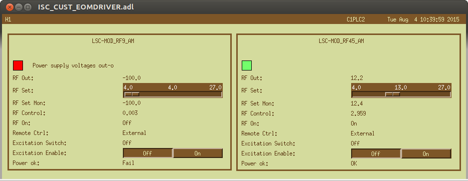
9MHz:
- We inserted a 10dB coupler into the 9MHz cable feeding the EOM. This dropped the drive signal from 4.7Vpkk to 4.5Vpkk - small enough the interferometer didn't care.
- It's output we directed into a two-way splitter, and fed both signals into a level 1 mixer.
- The output was low-passed through a 10MHz low pass.
- This gave us a DC level of 0.195V, and a noise of ~4.9nV/rtHz, resulting into a RIN of 2.5e-8.
- We hooked it up to an SR560 (Gain=1e4, AC coupled, band-passed with poles at 300Hz and 30kHz), and stuck it into LSC-EXTRA_AI_1 (IOP-LSC0_MADC2_TP_CH8)
- the ADC gain is 16384cts/10V
45MHz:
- We used the two remaining spare spigots of the 45MHz distribution rack, and mixed them in a level 3 mixer.
- Low-passed at 15MHz, we got a DC level of 0.57V, and a noise level of 120nV/rtHz...
- ... resulting in an outrageous RIN of 2e-7/rtHZ
- Again into an SR560 (Gain=1e3, AC coupled, band-passed with poles at 300Hz and 30kHz)
- and into LSC-EXTRA_AI_2 (IOP-LSC0_MADC2_TP_CH9)
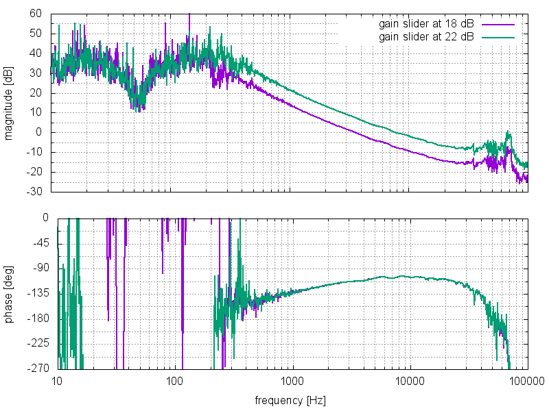
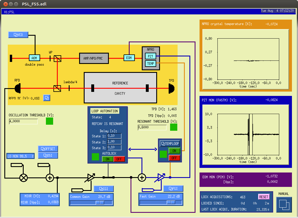
Plot 1 shows the RIN measured through the digital system
Calibration: LSC-EXTRA_AI_1 (IOP-LSC0_MADC2_TP_CH8): Gain=9.39e-5; p= 1, 728.178 65532 ; z= 300, 30000, 10062, 4973.6 9356.4, 33157, 426840 (dtt notation)
Calibration: LSC-EXTRA_AI_2 (IOP-LSC0_MADC2_TP_CH9): Gain=3.21e-4; p= 1, 728.178 65532 ; z= 300, 30000, 10062, 4973.6 9356.4, 33157, 426840 (dtt notation)
Note: the AA chasis itself has p= 728.178 65532 ; z= 10062, 4973.6 9356.4, 33157, 426840 (dtt notation)
Next Evan locked the interferometer, and we found a coherence of 0.9 between the 45MHz RIN (IOP-LSC0_MADC2_TP_CH9) and ASC_AS_C (IOP-ASC0_MADC6_TP_CH11) - this was oue best monitor for mystery noise.... BINGO
We also calibrated OMC_DCPD_A (IOP-LSC0_MADC0_TP_CH12) in Amps (today the whitening filters were off):
Calibration:Gain=7.726e-7; p= 7.689, 7.689, 728.178 65532 ; z= 78.912, 90.642, 13700, 17800, 10062, 4973.6 9356.4, 33157, 426840 (dtt notation)
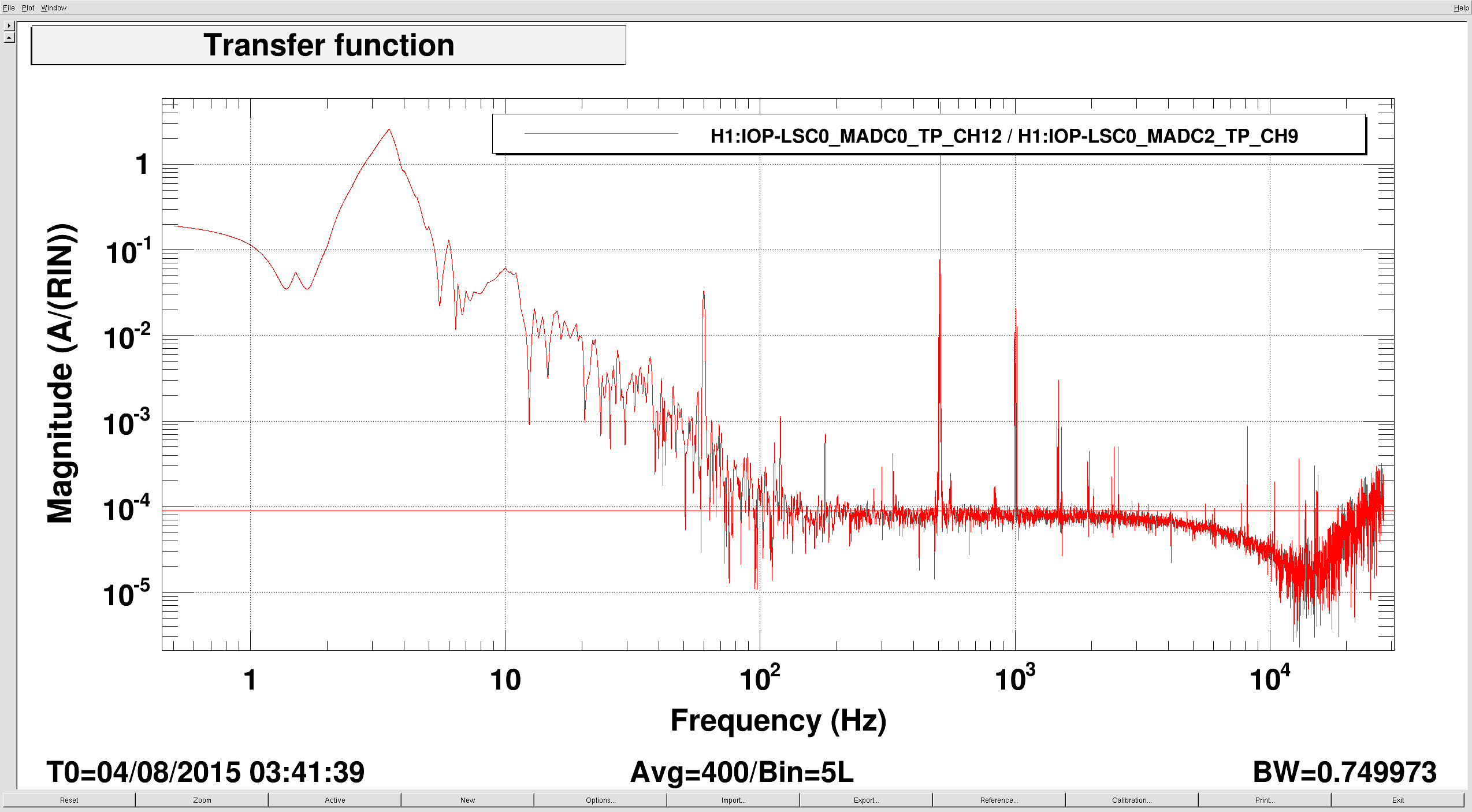
The noise level in OMC_DCPD_A was 7e-8mA/rtHz. Shot noise would be 5.7e-8mA/rtHz at 10mA.
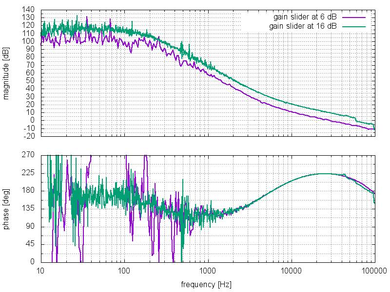
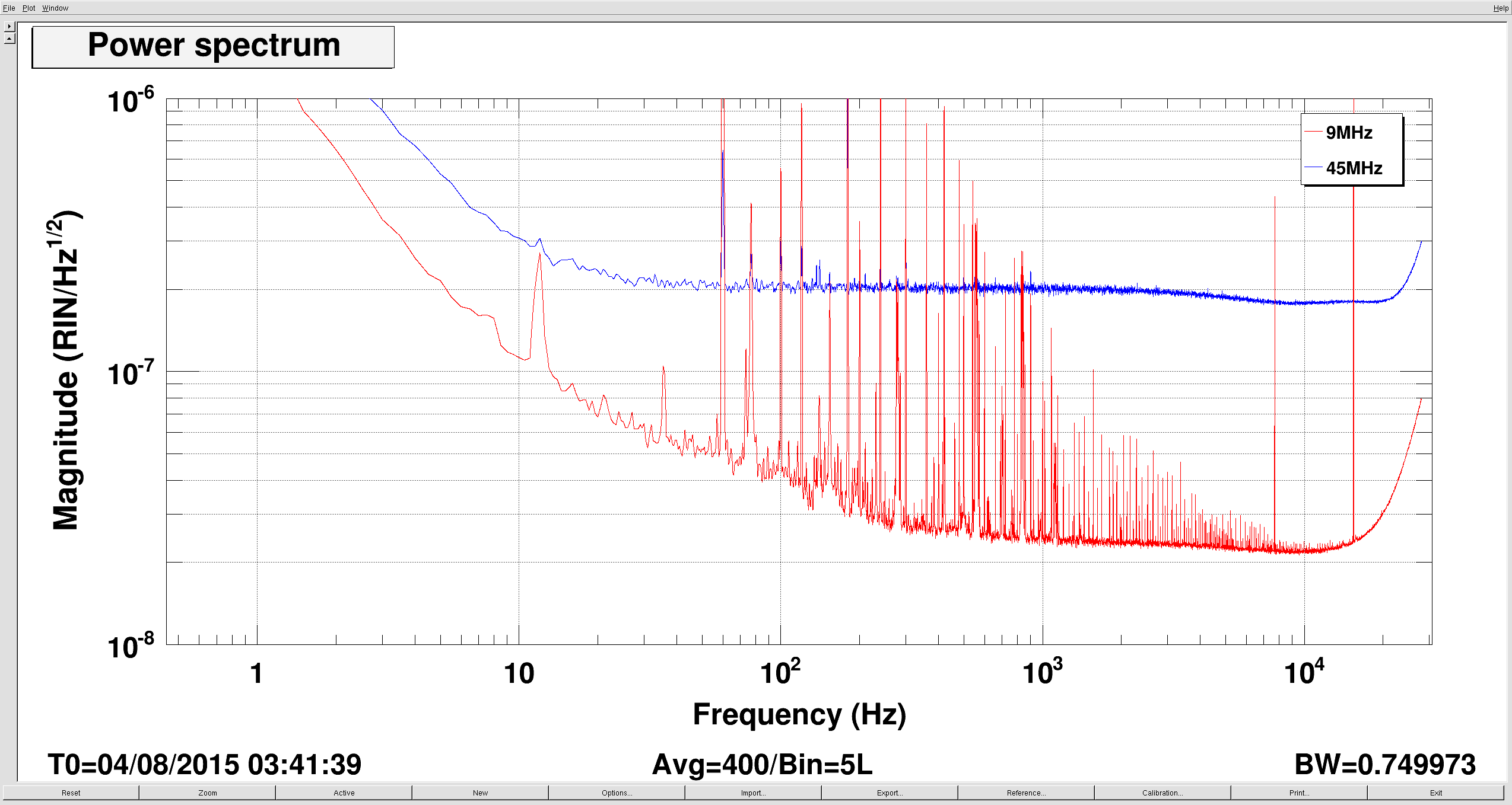
Using the coherence between OMC_DCPD_A and RF45 RIN we estimated the ransfer function to be about 9e-5 A/RIN per photo diode. (Plot2)
This let's us estimate the RF45 RIN contribution: 9e-5 A/RIN * 2e-7RIN/rtHz = 1.8e-8mA/rtHz. Very close to the 1.4mA/rtHz estimated in alog 19856.
We are a bit puzzled by the fact that this doesn't seem enough the explain the full elevated noise in DCPD_A: sqrt(1.8^2 + 5.7^2) = 6.0 < 7 (everything x1e-8mA/rtHz). (Plot3)
Plot 4 shows the coherence (ignore below 300Hz - the interferometer wasn't completely in low noise mode.


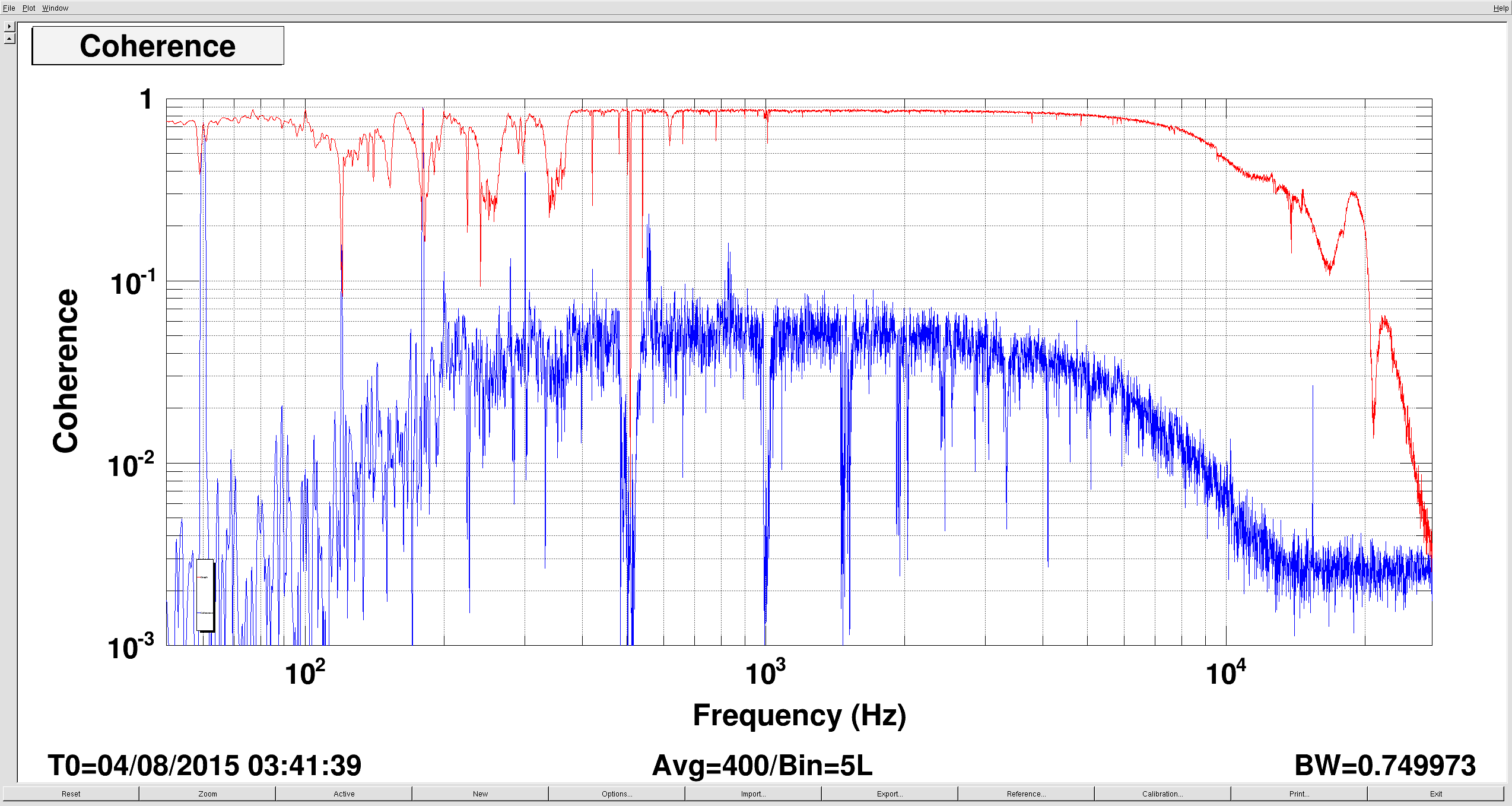

Note, a trend shows this railed negative at almost 1am last night (Aug 4, 07:47 UTC)
I don't remember the exact time but sometime before ~midnight last night, Sheila and I had found the ETMX ESD driver railed negative, and drove to the end station to fix it. All we did was power cycle the box - no cable plug/unplugging, and it came back for us.
Sorry we didn't log this last night. We left around 12:30am, so the railing that Betsy mentions happened when no one was on site, although we left the guardian request somewhere in a fully-locked state (probably Nom. Low Noise).
We don't see button pushing which would have lead to the rail in the middle of the night last night... see attached 24 hour plot.
In talking to Sheila, she fesses up to having an ETMx ESD neg rail earlier at ~11pm (shown on the plot if you look closely), which they caught and went down to Ex to clear in the same manner as above. They left just before it railed neg again - hence the no-auto-locking from then on.